Pages

Thursday, May 26, 2016

IR remote control system based on PIC microcontroller - CCS PIC C compiler

5-Channel IR RC5 remote control encoder/decoder using PIC18F4550 microcontroller
This topic shows how to build an infrared remote control transmitter and receiver using PIC18F4550 microcontroller and CCS PIC C compiler.
The IR system has two circuits: transmitter circuit and receiver circuit. Both circuits have the same microcontroller type which is PIC18F4550.
This system uses RC5 protocol from Philips. The following link shows how to decode RC5 IR remote control:
RC-5 remote control decoder with PIC18F4550 and CCS C
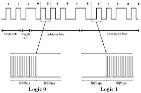
The RC5 protocol message is 14-bit data length which are 2 start bits, 1 toggle bit, 5 address bits and 6 command bits as shown in the following figure. The most important are the address and command bits.
RC-5 protocol coding 
The IR signal needs a carrier frequency and the carrier frequency of the RC5 protocol is 36KHz with a duty cycle of 25% to 33%.
The following figure shows a complete RC5 code with a simple example:
RC-5 IR remote control protocol encoder decoder 
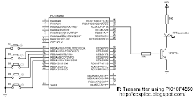
IR RC-5 remote control transmitter circuit (RC-5 Encoder):
The following image shows the transmitter circuit schematic of the IR system.
There are five pushbuttons in the circuit, each pushbutton sends a different IR code via an IR transmitter.
PIC18F4550 internal oscillator is used (8MHz) and MCLR is disabled.
RC5 IR remote control transmitter encoder circuit using PIC18F4550 and CCS PIC C
IR RC5 remote control transmitter circuit using PIC18F4550 CCS C code: 
To get a carrier frequency of 36KHz, PIC18F4550 PWM1 module is used with 25% duty cycle.
Logic 0 code with carrier frequency:
pwm_on();
delay_us(889);
pwm_off();
delay_us(889);

And logic 1 code with carrier frequency:
pwm_off();
delay_us(889);
pwm_on();
delay_us(889); 

In the circuit there are five pushbuttons: B1, B2, B3, B4 and B5, they send the following address and command codes:
B1: address = 0 and command = 0,
B2: address = 0 and command = 1,
B3: address = 0 and command = 2,
B4: address = 0 and command = 3,
B5: address = 0 and command = 4.
The two start bits are always 1's and the toggle bit maybe 1 or 0.
The following C code is the full code for this circuit and it is written with CCS PIC C compiler PCWHD version 5.0.51:
// PIC18F4550 IR RC5 encoder CCS PIC C compiler code
// http://ccspicc.blogspot.com/
// electronnote@gmail.com

#include <18F4550.h>
#fuses NOMCLR INTRC_IO
#use delay(clock = 8000000)
#use pwm (PWM1, FREQUENCY = 36KHz, DUTY = 25, PWM_OFF)

short toggle;
void send_ir_signal(int8 address, int8 command){
  int8 i = 0;
  // Start bits
  pwm_on();
  delay_us(889);
  pwm_off();
  delay_us(889);
  pwm_on();
  delay_us(889);
  pwm_off();
  // Toggle bit
  toggle = !toggle;
  if(toggle){
    delay_us(889);
    pwm_on();
    delay_us(889);
  }
  else {
    pwm_on();
    delay_us(889);
    pwm_off();
    delay_us(889);
  }
  // Address
  for(i = 0x10; i > 0; i = i >> 1){
    if( address & i ){
      pwm_off();
      delay_us(889);
      pwm_on();
      delay_us(889);}
    else {
      pwm_on();
      delay_us(889);
      pwm_off();
      delay_us(889);}
  }
  // Command
  for (i = 0x20; i > 0; i = i >> 1){
    if ( command & i ){
      pwm_off();
      delay_us(889);
      pwm_on();
      delay_us(889);}
    else {
      pwm_on();
      delay_us(889);
      pwm_off();
      delay_us(889);}
  }
   pwm_off();
}
void main(){
  setup_oscillator(OSC_8MHZ);            // Set internal oscillator to 8MHz
  setup_adc_ports(NO_ANALOGS);            // Configure AN0 and AN1 as analog inputs
  port_b_pullups(TRUE);
  output_b(0);
  set_tris_b(0x1F);
  delay_ms(100);                         // Wait 100ms
  while(TRUE){
    if(!input(PIN_B0)){
      send_ir_signal(0, 0);
      delay_ms(500);}
    if(!input(PIN_B1)){
      send_ir_signal(0, 1);
      delay_ms(500);}
    if(!input(PIN_B2)){
      send_ir_signal(0, 2);
      delay_ms(500);}
    if(!input(PIN_B3)){
      send_ir_signal(0, 3);
      delay_ms(500);}
    if(!input(PIN_B4)){
      send_ir_signal(0, 4);
      delay_ms(500);}
  }
}

IR RC-5 remote control transmitter circuit (RC-5 Decoder):
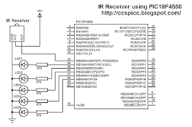
The RC5 IR receiver circuit schematic (RC5 decode) is shown below:
RC5 IR remote control receiver decoder circuit using PIC18F4550 and CCS PIC C
PIC18F4550 internal oscillator is used (8MHz) and MCLR is disabled.
In the receiver circuit there are 5 LEDs, each LED is controlled by one pushbutton on the transmitter circuit. The IR receiver receives IR signals transmitted from the IR transmitter on the transmitter circuit.
IR RC5 remote control receiver circuit using PIC18F4550 CCS C code:
The microcontroller waits until an IR signal is received (RB0 pin goes from high to low). After an IR signal is received the microcontroller checks if the received signal uses RC5 protocol, if so the microcontroller starts decoding the RC5 signal and the most important are the address bits and the command bits.
If address = 0 and command = 0: toggle LED1
If address = 0 and command = 1: toggle LED2
If address = 0 and command = 2: toggle LED3
If address = 0 and command = 3: toggle LED4
If address = 0 and command = 4: toggle LED5

The following C code is the full code for the receiver microcontroller:
// RC5 IR receiver(decoder) with PIC18F4550 CCS PIC C compiler code
// http://ccspicc.blogspot.com/
// electronnote@gmail.com

#include <18F4550.h>
#fuses NOMCLR INTRC_IO
#use delay(clock = 8000000)
#use fast_io(B)

int1 toggle;
unsigned int8 count, i, address, command;
short remote_read(){
  count = 0;
    // Check if the received signal uses RC5 protocol
    while((input(PIN_B0) == 0) && (count < 20)){
      count++;
      delay_us(50);}
    if( (count > 20) || (count < 14))      // Signal doesn't use RC5 protocol
      return FALSE;                            // Return
    count = 0;
    while((input(PIN_B0)) && (count < 20)){
      count++;
      delay_us(50);}
    if( (count > 20) || (count < 14))      // Signal doesn't use RC5 protocol
      return FALSE ;                            // Return
    count = 0;
    while((input(PIN_B0) == 0) && (count < 40)){
      count++;
      delay_us(50);}
    if( (count > 40) || (count < 14))      // Signal doesn't use RC5 protocol
      return FALSE ;                            // Return
    // End check (The received signal uses RC5 protocol)
    if(count > 30)
      delay_us(400);
    else           
      delay_us(1300);
    for(i = 0; i < 12; i++){
      if(i == 0){
        if(input(PIN_B0) == 1)   toggle = 0;
        else                     toggle = 1;
      }
      else {
        if(i < 6){                                //Read address bits
          if(input(PIN_B0) == 1) 
            bit_clear(address, (5 - i));          //Clear bit (5-i)
          else
            bit_set(address, (5 - i));           //Set bit (5-i)
        }
        else {                                 //Read command bits
          if(input(PIN_B0) == 1)  
            bit_clear(command, (11 - i));        //Clear bit (11-i)
          else                
            bit_set(command, (11 - i));          //Set bit (11-i)
        }
      }
      delay_us(1778);
  }
  address &= 0x1F;
  command &= 0x3F;
  return TRUE;
}
void main(){
  setup_oscillator(OSC_8MHZ);                // Set internal oscillator to 8MHz
  setup_adc_ports(NO_ANALOGS);               // Configure AN pins as digital
  output_b(0);                               // PORTB initial state
  set_tris_b(1);                             // Configure RB0 pin as input
  delay_ms(100);                             // Wait 100ms
  while(TRUE){
    while(input(PIN_B0));                    // Wait until RB0 pin falls
    if(remote_read()){
      if((address == 0) && (command == 0))
        output_toggle(PIN_B1);
      if((address == 0) && (command == 1))
        output_toggle(PIN_B2);
      if((address == 0) && (command == 2))
        output_toggle(PIN_B3);
      if((address == 0) && (command == 3))
        output_toggle(PIN_B4);
      if((address == 0) && (command == 4))
        output_toggle(PIN_B5);
    }
    delay_ms(10);  
  }
}

IR remote control system based on PIC microcontroller video: 
The following video shows a hardware circuits for the project.

Tuesday, May 24, 2016

Interfacing unipolar stepper motor with PIC18F4550 microcontroller

Unipolar stepper motor drive with PIC18F4550 microcontroller 
Unipolar 5V stepper motor 
After interfacing PIC18F4550 microcontroller with bipolar stepper motor in the following topic:
CD-ROM Bipolar stepper motor drive using PIC18F4550 and CCS PIC C
Now let's see how to drive a unipolar stepper motor using PIC18F4550 and CCS PIC C compiler.
Usually the bipolar stepper motor has 2 colis and therefore it has 4 wires, and the unipolar has 4 coils which are connected as shown in the following figure:
Unipolar stepper motor coils PIC18F4550
The unipolar stepper motor can be controlled in full step mode or half step mode, the usual method is the full step driving mode which gives higher torque. The following table shows driving sequences:
Unipolar stepper motor driving sequence PIC18F4550
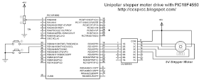
Interfacing PIC18F4550 with unipolar stepper motor circuit:
In the circuit there are 2 pushbuttons which are connected to RB0 and RB1 pins, they are used to choose motor rotation direction. PortB internal pull-ups are enabled in the software.
To control the stepper motor speed a potentiometer (10K) is used and it is connected to analog channel 0(AN0).
ULN2003 (or ULN2004) chip is used to energize the stepper motor coils.
The ULN2003(ULN2004) is a Darlington transistor array which contains seven open collector Darlington pairs with common emitters. For stepper motor controller we need 4 transistors form this chip which means 4 inputs and 4 outputs are needed.

Interfacing unipolar stepper motor with PIC18F4550 ULN2003 circuit CCS PIC C
Instead of the ULN2003 chip, another chip can be used which is L293D dual H-bridge circuits as shown in the circuit schematic below.
For the L293D chip VS voltage always +5V and VSS voltage is the same as the motor voltage for example if the motor voltage is 12V, VSS should be connected to +12V power supply.

Interfacing unipolar stepper motor with PIC18F4550 L293D circuit CCS PIC C
PIC18F4550 internal oscillator is used (8MHz) and MCLR pin function is disabled.
Interfacing PIC18F4550 with unipolar stepper motor CCS C code:
A pot connected to AN0 is used to control the speed of the stepper motor. The microcontroller reads the analog data from AN0 and uses the digital value to change the delay between motor driving sequences.

// Interfacing PIC18F4550 with unipolar stepper motor CCS C code
// http://ccspicc.blogspot.com/
// electronnote@gmail.com

#include <18F4550.h>
#fuses NOMCLR INTRC_IO
#use delay(clock = 8000000)
#use fast_io(B)
#use fast_io(D)

unsigned int8 speed_;
void main()
{
   setup_oscillator(OSC_8MHZ);              // Set internal oscillator to 8MHz
   setup_adc(ADC_CLOCK_DIV_8);              // Set ADC conversion time to 8Tosc
   setup_adc_ports(AN0);                    // Configure RA0(AN0)as analog
   set_adc_channel(0);                      // Select channel 0 input
   port_b_pullups(TRUE);
   output_b(0);
   set_tris_b(3);
   output_d(0);
   set_tris_d(0);
   delay_ms(100);
   while(TRUE)
   {
      output_d(0);
      while( ! input(PIN_B0))
      {
         speed_ = read_adc();
         if(speed_ < 2)
            speed_ = 2;
         output_d(0b00000011);
         delay_ms(speed_);
         output_d(0b00000110);
         delay_ms(speed_);
         output_d(0b00001100);
         delay_ms(speed_);
         output_d(0b00001001);
         delay_ms(speed_);
      }
      while( ! input(PIN_B1))
      {
         speed_ = read_adc();
         if(speed_ < 2)
            speed_ = 2;
         output_d(0b00001001);
         delay_ms(speed_);
         output_d(0b00001100);
         delay_ms(speed_);
         output_d(0b00000110);
         delay_ms(speed_);
         output_d(0b00000011);
         delay_ms(speed_);
      }
   }
}

Interfacing PIC18F4550 with unipolar stepper motor video:
The following video shows project hardware circuit.

Unipolar stepper motor control using PIC16F877A microcontroller

Interfacing unipolar stepper motor with PIC16F877A
This post shows how to control speed and rotation direction of unipolar stepper motor using PIC16F877A microcontroller and CCS PIC C compiler.
Related topic:
Bipolar stepper motor control with PIC16F877A microcontroller
Usually the unipolar stepper motor has 5 wires one for motor supply and the other for coils. This motor has 4 coils and they are connected as shown in the figure below:
Unipolar stepper motor coils control
The unipolar stepper motor can be controlled in full step mode or half step mode, the usual method is the full step driving mode. The following table shows driving sequences:
Unipolar stepper motor control sequence PIC16F877A
Interfacing PIC16F877A with unipolar stepper motor circuit:
In the circuit there are 2 pushbuttons which are connected to RB0 and RB1 pins, they are used to choose motor rotation direction.
To control the stepper motor speed a potentiometer (10K) is used and it is connected to analog channel 0(AN0).

ULN2003 (or ULN2004) chip is used to energize the stepper motor coils.
The ULN2003(ULN2004) is a Darlington transistor array which contains seven open collector Darlington pairs with common emitters. For stepper motor controller we need 4 transistors form this chip which means 4 inputs and 4 outputs are needed.
Interfacing PIC16F877A microcontroller with unipolar stepper motor control circuit using ULN2003 CCS PIC C
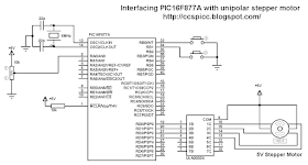
Instead of the ULN2003 chip, another chip can be used which is L293D dual H-bridge circuits as shown in the circuit schematic below.
For the L293D chip VS voltage always +5V and VSS voltage is the same as the motor voltage for example if the motor voltage is 12V VSS should be connected to +12V power supply.
Interfacing PIC16F877A microcontroller with unipolar stepper motor control circuit using L293D CCS PIC C
Interfacing PIC16F877A with unipolar stepper motor CCS C code:
A pot connected to AN0 is used to control the speed of the stepper motor. The microcontroller reads the analog data from AN0 and uses the digital value to change the delay between motor driving sequences.
// Interfacing PIC16F877A microcontroller with unipolar stepper motor CCS C code
// http://ccspicc.blogspot.com/
// electronnote@gmail.com

#include <16F877A.h>
#fuses HS,NOWDT,NOPROTECT,NOLVP                       
#use delay(clock = 8000000)
#use fast_io(B)
#use fast_io(D)

unsigned int8 speed_;
void main(){
  output_b(0);
  set_tris_b(0x03);
  port_b_pullups(TRUE);
  output_d(0);
  set_tris_d(0);
  setup_adc(ADC_CLOCK_DIV_32);      // Set ADC conversion time to 32Tosc
  setup_adc_ports(AN0);             // Configure AN0 as analog  
  set_adc_channel(0);               // Select channel 0 input
  delay_ms(100);                    // Wait 100ms
  while(TRUE)
   {
      output_d(0);
      while( ! input(PIN_B0))
      {
         speed_ = read_adc();
         if(speed_ < 2)
            speed_ = 2;
         output_d(0b00000011);
         delay_ms(speed_);
         output_d(0b00000110);
         delay_ms(speed_);
         output_d(0b00001100);
         delay_ms(speed_);
         output_d(0b00001001);
         delay_ms(speed_);
      }
      while( ! input(PIN_B1))
      {
         speed_ = read_adc();
         if(speed_ < 2)
            speed_ = 2;
         output_d(0b00001001);
         delay_ms(speed_);
         output_d(0b00001100);
         delay_ms(speed_);
         output_d(0b00000110);
         delay_ms(speed_);
         output_d(0b00000011);
         delay_ms(speed_);
      }
   }
}

Interfacing PIC16F877A with unipolar stepper motor video:
The following video shows a hardware circuit for this project.

Monday, May 23, 2016

Interfacing PIC16F84A microcontroller with stepper motor

CD-ROM bipolar stepper motor drive with PIC16F84A and CCS PIC C compiler
This topic shows circuit schematic and C code for interfacing PIC16F84A microcontroller with CD-ROM bipolar stepper motor.
Related Topics:
CD-ROM Bipolar stepper motor drive using PIC18F4550 and CCS PIC C
Bipolar stepper motor control with PIC16F877A microcontroller
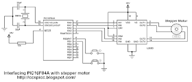
The following circuit schematic shows the connection between the microcontroller PIC16F84A and the stepper motor where a dual H-bridge circuit which is L293D chip is used between them.
Interfacing PIC16F84A with stepper motor circuit CCS PIC C
The two pushbuttons are used to choose motor rotation direction.
Interfacing PIC16F84A microcontroller with stepper motor CCS PIC C code:
The motor speed is fixed by the code but we can change it by changing the delay between the four phases.
// Interfacing PIC16F84A with CD-ROM bipolar stepper motor CCS C code
// http://ccspicc.blogspot.com/
// electronnote@gmail.com

#include <16F84A.h>
#fuses HS,NOWDT,PUT,NOPROTECT
#use delay(clock = 8000000)
#use fast_io(A)
#use fast_io(B)

void main()
{
   output_a(0);
   set_tris_a(0);
   port_b_pullups(TRUE);
   output_b(0);
   set_tris_b(3);
   while(TRUE)
   {
      output_a(0);
      while(!input(PIN_B0))
      {
         output_a(0b00000110);
         delay_ms(5);
         output_a(0b00000101);
         delay_ms(5);
         output_a(0b00001001);
         delay_ms(5);
         output_a(0b00001010);
         delay_ms(5);
      }
      while(!input(PIN_B1))
      {
         output_a(0b00000101);
         delay_ms(5);
         output_a(0b00000110);
         delay_ms(5);
         output_a(0b00001010);
         delay_ms(5);
         output_a(0b00001001);
         delay_ms(5);
      }
   }
}

Interfacing PIC16F84A microcontroller with stepper motor video: The following video shows a hardware circuit of this project.

Sunday, May 22, 2016

CD-ROM Bipolar stepper motor drive using PIC18F4550 and CCS PIC C

Stepper motor interfacing with PIC18F4550 microcontroller
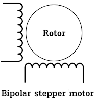
Most of cd-rom or dvd-rom drives has a bipolar stepper motor, this motor has two windings and each winding has 2 inputs which means that this type of motor has 4 wires.
CD-ROM bipolar stepper motor windings PIC18F4550 projects
This topic shows circuit schematic and C code for controlling the bipolar stepper motor speed and direction using PIC18F4550 microcontroller.
The stepper motor can be controlled in full step mode or half step mode. The full step mode is a little bit easier than the half step control mode. In this topic the full step control mode is used.
To control the bipolar stepper motor we need two H-bridge circuits and for that L293D motor driver chip is used, this cheap chip can work as a dual H-bridge drivers.
In the full step control mode always both windings are energized according to the following two tables where table1 shows the driving sequence for rotation direction 1:

stepper motor phases drive PIC18F4550 projects
And the following table shows driving sequence for the other rotation direction:
stepper motor phases control PIC18F4550 projects
Interfacing PIC18F4550 with bipolar stepper motor circuit:
The following image shows circuit schematic diagram of this project a potentiometer connected to AN0 channel is used to control the speed as well as the rotation direction of the stepper motor as shown in the video below.

Interfacing PIC18F4550 microcontroller with CD-ROM stepper motor speed direction control L293D CCS PIC C
PIC18F4550 internal oscillator is used (8MHz) and MCLR pin function is disabled.
Interfacing PIC18F4550 with bipolar stepper motor CCS C code:
The following code is the full C code of this project where a potentiometer which is connected to channel AN0 is used to control the rotation direction and the speed of the stepper motor.
The microcontroller reads the analog value from the output of the pot and uses the digital value to control the rotation direction and the speed with ADC resolution of 8 bits.
// Interfacing PIC18F4550 with CD-ROM bipolar stepper motor CCS C code
// http://ccspicc.blogspot.com/
// electronnote@gmail.com

#include <18F4550.h>
#fuses NOMCLR INTRC_IO
#use delay(clock = 8000000)
#use fast_io(D)

unsigned int8 speed_, value;
void main()
{
   setup_oscillator(OSC_8MHZ);              // Set internal oscillator to 8MHz
   setup_adc(ADC_CLOCK_DIV_8);              // Set ADC conversion time to 8Tosc
   setup_adc_ports(AN0);                    // Configure RA0(AN0)as analog
   set_adc_channel(0);                      // Select channel 0 input
   output_d(0);
   set_tris_d(0);
   delay_ms(100);                           // Wait 100ms
   while(TRUE)
   {
      value = read_adc();
      if(value  < 2)value = 1;
      if(value  < 0x80)
      {
         speed_ = value;
         output_d(0b00000110);
         delay_ms(speed_);
         output_d(0b00000101);
         delay_ms(speed_);
         output_d(0b00001001);
         delay_ms(speed_);
         output_d(0b00001010);
         delay_ms(speed_);
      }
      else if(value  > 0x80)
      {
         speed_ = 256 - value;
         output_d(0b00000101);
         delay_ms(speed_);
         output_d(0b00000110);
         delay_ms(speed_);
         output_d(0b00001010);
         delay_ms(speed_);
         output_d(0b00001001);
         delay_ms(speed_);
      }
   }
}

Interfacing PIC18F4550 with bipolar stepper motor video:
The following video shows the project in hardware circuit.

Saturday, May 21, 2016

Bipolar stepper motor control with PIC16F877A microcontroller

Cd-Rom bipolar stepper motor control using PIC16F877A microcontroller and CCS PIC C compiler
Most of cd-rom or dvd-rom drives has a bipolar stepper motor, this motor has two windings and each winding has 2 inputs which means that this type of motor has 4 wires.
Cd rom bipolar stepper motor windings 
This topic shows circuit schematic and C code for controlling the bipolar stepper motor speed and direction using PIC16F877A microcontroller.
The stepper motor can be controlled in full step mode or half step mode. The full step mode is a little bit easier than the half step control mode. In this topic the full step control mode is used.
To control the bipolar stepper motor we need two H-bridge circuits and for that L293D motor driver chip is used, this cheap chip can work as a dual H-bridge drivers.
In the full step control mode always both windings are energized according to the following two tables where table1 shows the driving sequence for rotation direction 1:
Cd rom bipolar stepper motor driving sequence direction control 1
And the following table shows driving sequence for the other rotation direction:
Cd rom bipolar stepper motor driving sequence direction control 2
Interfacing PIC16F877A with bipolar stepper motor circuit:
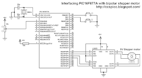
The following image shows circuit schematic diagram of this project where two pushbuttons are used to choose motor rotation direction and a potentiometer to control motor speed. PortB internal pull-ups are enabled in the C code.
Bipolar stepper motor speed and direction control using PIC16F877A and L293D circuit CCS PIC C
Interfacing PIC16F877A with bipolar stepper motor CCS C code:
A pot connected to AN0 is used to control the speed of the stepper motor. The microcontroller reads the analog data from AN0 and uses the digital value to change the delay between motor driving phases and when the delay increases the motor speed decreases and vise versa.
The two pushbuttons which are connected to RB0 and RB1 are used to choose motor rotation direction and when RB0 button pressed the driving sequence follows the first table above and when RB1 button is pressed the driving sequence follows the second table.
8-bit ADC resolution is used.
// Interfacing PIC16F877A with cd-rom bipolar stepper motor
// http://ccspicc.blogspot.com/
// electronnote@gmail.com

#include <16F877A.h>
#fuses HS,NOWDT,NOPROTECT,NOLVP                       
#use delay(clock = 8000000)
#use fast_io(B)
#use fast_io(D)

unsigned int8 speed_;
void stepper_move(short direction_){
  if(direction_){ 
   output_d(0b00000110);
   delay_ms(speed_);
   output_d(0b00000101);
   delay_ms(speed_);
   output_d(0b00001001);
   delay_ms(speed_);
   output_d(0b00001010);
   delay_ms(speed_);
  }
  else{
   output_d(0b00000101);
   delay_ms(speed_);
   output_d(0b00000110);
   delay_ms(speed_);
   output_d(0b00001010);
   delay_ms(speed_);
   output_d(0b00001001);
   delay_ms(speed_);
  }
}
void main(){
  output_b(0);
  set_tris_b(0x03);
  port_b_pullups(TRUE);
  output_d(0);
  set_tris_d(0);
  setup_adc(ADC_CLOCK_DIV_32);      // Set ADC conversion time to 32Tosc
  setup_adc_ports(AN0);             // Configure AN0 as analog  
  set_adc_channel(0);               // Select channel 0 input
  delay_ms(100);                    // Wait 100ms
  while(TRUE){
   output_d(0);
   while(!input(PIN_B0)){
    speed_ = read_adc();
    if(speed_ < 2) speed_ = 2;
    stepper_move(0);
   }
   while(!input(PIN_B1)){
    speed_ = read_adc();
    if(speed_ < 2) speed_ = 2;
    stepper_move(1);
   }
  }
}

Interfacing PIC16F877A with bipolar stepper motor video:
The following video shows the project in hardware circuit.

Thursday, May 19, 2016

Interfacing PIC18F4550 with DHT22(AM2302-RHT03) digital humidity and temperature sensor

Interfacing PIC18F4550 microcontroller with DHT22 sensor using CCS PIC C compiler
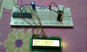
PIC18F4550 projects DHT22 sensor hardware circuit
This topic shows how to interface PIC18F4550 microcontroller with DHT22 sensor with hardware circuit.
Related topic:
The following topic shows PIC18F4550 microcontroller and DHT22 Proteus simulation with some details about this sensor.

PIC18F4550 microcontroller and DHT22(AM2302) sensor circuit + Proteus simulation
Interfacing PIC18F4550 with DHT22(AM2302 - RHT03) sensor circuit:
The following circuit schematic shows complete project circuit.

Interfacing PIC18F4550 with DHT22(AM2302-RHT03) digital humidity and temperature sensor hardware circuit CCS PIC C code
The circuit is simple, there is the microcontroller PIC18F4550, DHT22 sensor and 1602 LCD to display humidity and temperature results.
PIC18F4550 uses its internal oscillator @ 8MHz and mclr pin function is disabled.
Interfacing PIC18F4550 with DH22(AM2302-RHT03) sensor CCS C code:
The interfacing code is written with CCS PIC C compiler PCWHD version 5.051.
If you want to understand the code please read the DHT22 datasheet.
Variables Time_out and k are used to test reading time to avoid wrong data reception or microcontroller hanging.

// Interfacing PIC18F4550 with DHT22(AM2302 - RHT03) sensor CCS C code
// http://ccspicc.blogspot.com/
// electronnote@gmail.com

//LCD module connections
#define LCD_RS_PIN PIN_D0
#define LCD_RW_PIN PIN_D1
#define LCD_ENABLE_PIN PIN_D2
#define LCD_DATA4 PIN_D3
#define LCD_DATA5 PIN_D4
#define LCD_DATA6 PIN_D5
#define LCD_DATA7 PIN_D6
//End LCD module connections

#include <18F4550.h>
#fuses NOMCLR INTRC_IO
#use delay(clock = 8000000)
#include <lcd.c>
#use fast_io(B)
// Connection pin between PIC18F4550 and DHT22 sensor
#BIT Data_Pin = 0xF81.0                       // Pin mapped to PORTB.0
#BIT Data_Pin_Direction = 0xF93.0             // Pin direction mapped to TRISB.0

char message1[] = "Temp = 00.0 C";
char message2[] = "RH   = 00.0 %";
short Time_out ;
unsigned int8 T_byte1, T_byte2, RH_byte1, RH_byte2, CheckSum ;
unsigned int16 Temp, RH;
void start_signal(){
  Data_Pin_Direction = 0;              // Configure connection pin as output
  Data_Pin = 0;                        // Connection pin output low
  delay_ms(25);
  Data_Pin = 1;                        // Connection pin output high
  delay_us(30);
  Data_Pin_Direction = 1;              // Configure connection pin as input
}
short check_response(){
  delay_us(40);
  if(!Data_Pin){                     // Read and test if connection pin is low
    delay_us(80);
    if(Data_Pin){                    // Read and test if connection pin is high
      delay_us(50);
      return 1;}
    }
}
unsigned int8 Read_Data(){
  unsigned int8 i, k, _data = 0;     // k is used to count 1 bit reading duration
  if(Time_out)
    break;
  for(i = 0; i < 8; i++){
    k = 0;
    while(!Data_Pin){                          // Wait until pin goes high
      k++;
      if (k > 100) {Time_out = 1; break;}
      delay_us(1);}
    delay_us(30);
    if(!Data_Pin)
      bit_clear(_data, (7 - i));               // Clear bit (7 - i)
    else{
      bit_set(_data, (7 - i));                 // Set bit (7 - i)
      while(Data_Pin){                         // Wait until pin goes low
      k++;
      if (k > 100) {Time_out = 1; break;}
      delay_us(1);}
    }
  }
  return _data;
}
void main(){
  setup_oscillator(OSC_8MHZ);                // Set internal oscillator to 8MHz
  setup_adc_ports(NO_ANALOGS);                // Configure AN pins as digital
  lcd_init();                                 // Initialize LCD module
  lcd_putc('\f');                             // LCD clear 
  while(TRUE){
    delay_ms(1000);
    Time_out = 0;
    Start_signal();
    if(check_response()){                    // If there is response from sensor
      RH_byte1 = Read_Data();                 // read RH byte1
      RH_byte2 = Read_Data();                 // read RH byte2
      T_byte1 = Read_Data();                  // read T byte1
      T_byte2 = Read_Data();                  // read T byte2
      Checksum = Read_Data();                 // read checksum
      if(Time_out){                           // If reading takes long time
        lcd_putc('\f');                       // LCD clear
        lcd_gotoxy(5, 1);                     // Go to column 5 row 1
        lcd_putc("Time out!");
      }
      else{
       if(CheckSum == ((RH_Byte1 + RH_Byte2 + T_Byte1 + T_Byte2) & 0xFF)){
        RH = RH_byte1;
        RH = (RH << 8) | RH_byte2;
        Temp = T_byte1;
        Temp = (Temp << 8) | T_byte2;
        if (Temp > 0X8000){
         message1[6] = '-';
         Temp = Temp & 0X7FFF; }
        else
         message1[6] = ' ';
        message1[7]  = (Temp / 100) % 10  + 48;
        message1[8]  = (Temp / 10) % 10  + 48;
        message1[10] = Temp % 10  + 48;
        message2[7]  = (RH / 100) % 10 + 48;
        message2[8]  = (RH / 10) % 10 + 48;
        message2[10] = RH % 10 + 48;
        message1[11] = 223;                   // Degree symbol
        lcd_putc('\f');                       // LCD clear    
        lcd_gotoxy(1, 1);                     // Go to column 1 row 1
        printf(lcd_putc, message1);           // Display message1
        lcd_gotoxy(1, 2);                     // Go to column 1 row 2
        printf(lcd_putc, message2);           // Display message2
       }
        else {
          lcd_putc('\f');                     // LCD clear
          lcd_gotoxy(1, 1);                   // Go to column 1 row 1
          lcd_putc("Checksum Error!");
        }
      }
    }
    else {
      lcd_putc('\f');             // LCD clear
      lcd_gotoxy(3, 1);           // Go to column 3 row 1
      lcd_putc("No response");
      lcd_gotoxy(1, 2);           // Go to column 1 row 2
      lcd_putc("from the sensor");
    }
  }
}

Interfacing PIC18F4550 with DHT22 sensor video:
The following video shows hardware circuit of this project.