Pages

Tuesday, September 20, 2016

433MHz Radio Frequency (RF) transmitter and receiver using PIC12F1822

433MHz RF Remote control system with PIC microcontroller
This project shows how to use low cost 433MHz RF transmitter/receiver modules to build a 5-channel wireless RF remote control system using 2 x PIC12F1822 microcontrollers.
The used RF modules in this project are cheap and easy to use with any microcontroller. These modules are shown below with pin configuration:
433MHz 315 MHz transmitter receiver
Communication protocol:
In this 433MHz RF project data is transmitted from the transmitter circuit to the receiver circuit using NEC protocol. The NEC protocol uses pulse distance encoding of the bits. Each pulse is a 562.5µs long.
Logic 0: 562.5µs pulse burst followed by a 562.5µs space, with a total transmit time of 1125µs (562.5 x 2).
Logic 1: a 562.5µs pulse burst followed by a 1687.5µs (562.5 x 3) space, with a total transmit time of 2250µs (562.5 x 4).
The following topic shows how to decode an IR remote control uses the NEC communication protocol:
Extended NEC Protocol Decoder Using PIC12F1822 Microcontroller

Components List:
RF Transmitter Circuit:
  • PIC12F1822 Microcontroller
  • 433MHz or 315MHz RF Transmitter
  • 5 Push Buttons
  • +5V Power Source
  • Protoboard
  • Jumper Wires
RF Receiver Circuit:
  • PIC12F1822 Microcontroller
  • 433MHz or 315MHz RF Receiver
  •  100uf Capacitor
  • 5 LEDs
  • 5 x 470 Ohm Resistors
  • +5V Power Source
  • Protoboard
  • Jumper Wires
5-Channel 433MHz RF remote control transmitter circuit:
The RF transmitter circuit schematic is shown below.
433MHz radio frequency RF transmitter circuit using PIC microcontroller
In the circuit there 5 push buttons and each button sends a different RF signal code. The RF transmitter is the element that sends the RF signals to the RF receiver circuit.
PIC12F1822 internal pull-ups are enabled by the software and the internal oscillator is used as usual.
5-Channel 433MHz RF remote control transmitter using PIC12F1822 CCS PIC C code:
In the circuit there are 5 push buttons connected to RA0, RA1, RA2, RA3 and RA4 which means that pins must be configured as inputs and the RA5 pin as output.
Internal pull-ups are enabled for the input pins with the following line:
port_a_pullups(0x1F);
The five buttons transmit the following signals respectively:
0x40BF00FF -- 0x40BF807F -- 0x40BF40BF -- 0x40BF20DF -- 0x40BFA05F
1s and 0s are transmitted as:
Transmit 1 : output_high(PIN_A5);
Transmit 0: output_low(PIN_A5);
For example the transmission of 9ms pulse and 4.5ms space:
// Send 9ms pulse
  output_high(PIN_A5);
  delay_ms(9);
  // Send 4.5ms space
  output_low(PIN_A5);
  delay_us(4500);

CCS C code:
// NEC protocol 433MHz RF remote control transmitter using PIC12F1822 CCS PIC C code
// http://ccspicc.blogspot.com/
// electronnote@gmail.com
// Use at your own risk

#include <12F1822.h>
#fuses NOMCLR INTRC_IO PLL_SW
#use delay(clock=32000000)
#use fast_io(A)

void send_signal(unsigned int32 number){
  int8 i;
  // Send 9ms pulse
  output_high(PIN_A5);
  delay_ms(9);
  // Send 4.5ms space
  output_low(PIN_A5);
  delay_us(4500);
  // Send data
  for(i = 0; i < 32; i++){
    // If bit is 1 send 560us pulse and 1680us space
    if(bit_test(number, 31 - i)){
      output_high(PIN_A5);
      delay_us(560);
      output_low(PIN_A5);
      delay_us(1680);
    }
    // If bit is 0 send 560us pulse and 560us space
    else{
      output_high(PIN_A5);
      delay_us(560);
      output_low(PIN_A5);
      delay_us(560);
    }
  }
  // Send end bit
  output_high(PIN_A5);
  delay_us(560);
  output_low(PIN_A5);
  delay_us(560);
}
void main() {
  setup_oscillator(OSC_8MHZ | OSC_PLL_ON);            // Set internal oscillator to 32MHz (8MHz and PLL)
  output_a(0);
  set_tris_a(0x1F);                                   // Configure RA5 pin as output and others as inputs
  port_a_pullups(0x1F);                               // Enable internal pull-ups for pins RA0,RA1,RA2,RA3 & RA4
  while(TRUE){
    while(!input(PIN_A0)){
      send_signal(0x40BF00FF);
      delay_ms(500);
    }
    while(!input(PIN_A1)){
      send_signal(0x40BF807F);
      delay_ms(500);
    }
    while(!input(PIN_A2)){
      send_signal(0x40BF40BF);
      delay_ms(500);
    }
    while(!input(PIN_A3)){
      send_signal(0x40BF20DF);
      delay_ms(500);
    }
    while(!input(PIN_A4)){
      send_signal(0x40BFA05F);
      delay_ms(500);
    }
  }
}
5-Channel 433MHz RF remote control receiver circuit:
433MHz radio frequency RF receiver circuit using PIC microcontroller
In the 433MHz RF receiver circuit there are 5 LEDs and an RF receiver. The RF receiver receives radio signals transmitted from the RF transmitter. Each LED is remotely controlled from one button in the transmitter circuit.
PIC12F1822 internal oscillator is used and MCLR pin is configured as a digital input pin.
5-Channel 433MHz RF remote control receiver using PIC12F1822 CCS PIC C code:
As in the RF transmitter the internal oscillator of the RF receiver microcontroller is used.
Timer1 is configured to increment every 1us and it is used to measure pulses and spaces duration (@ 32MHz mcu frequency).
SETUP_TIMER_1(T1_INTERNAL | T1_DIV_BY_8);
For example to check the 9ms pulse the following lines are used:
// Check 9ms pulse (remote control sends logic high)
  SET_TIMER1(0);
  while(input(IR_Sensor) && (count < 9500))
    count = GET_TIMER1();
  if( (count > 9499) || (count < 8500))
    return FALSE;

And checking the 4.5ms space as follows:
// Check 4.5ms space (remote control sends logic low)
  SET_TIMER1(0);
  count = 0;
  while((!input(IR_Sensor)) && (count < 5000))
    count = GET_TIMER1();
  if( (count > 4999) || (count < 4000))
    return FALSE;

Full Code:
// NEC protocol 433MHz RF remote control receiver using PIC12F1822 CCS PIC C code
// http://ccspicc.blogspot.com/
// electronnote@gmail.com
// Use at your own risk

#include <12F1822.h>
#fuses NOMCLR INTRC_IO PLL_SW
#use delay(clock=32000000)
#use fast_io(A)
#define RF_Receiver PIN_A3

unsigned int32 rf_code;
short nec_remote_read(){
  unsigned int16 count = 0;
  unsigned int8 i;
  // Check 9ms pulse (RF remote control sends logic high)
  SET_TIMER1(0);
  while(input(RF_Receiver) && (count < 9500))
    count = GET_TIMER1();
  if( (count > 9499) || (count < 8500))
    return FALSE;
  // Check 4.5ms space (RF remote control sends logic low)
  SET_TIMER1(0);
  count = 0;
  while((!input(RF_Receiver)) && (count < 5000))
    count = GET_TIMER1();
  if( (count > 4999) || (count < 4000))
    return FALSE;
  // Read RF message (32 bits)
  for(i = 0; i < 32; i++){
    SET_TIMER1(0);
    count = 0;
    while(input(RF_Receiver) && (count < 650))
      count = GET_TIMER1();
    if( (count > 649) || (count < 500))
      return FALSE;
    count = 0;
    SET_TIMER1(0);
    while((!input(RF_Receiver)) && (count < 1800))
      count = GET_TIMER1();
    if( (count > 1799) || (count < 400))
      return FALSE;
    if( count > 1000)                                 // If space width > 1ms
      bit_set(rf_code, (31 - i));                     // Write 1 to bit (31 - i)
    else                                              // If space width < 1ms
      bit_clear(rf_code, (31 - i));                   // Write 0 to bit (31 - i)
  }
  return TRUE;
}
void main() {
  setup_oscillator(OSC_8MHZ | OSC_PLL_ON);            // Set internal oscillator to 32MHz (8MHz and PLL)
  output_a(0);
  set_tris_a(8);
  SETUP_TIMER_1(T1_INTERNAL | T1_DIV_BY_8);
  while(TRUE){
    while(!input(RF_Receiver));                       // Wait until RF_Receiver pin raises
    if(nec_remote_read()){
      if(rf_code == 0x40BF00FF)
        output_toggle(PIN_A0);
      if(rf_code == 0x40BF807F)
        output_toggle(PIN_A1);
      if(rf_code == 0x40BF40BF)
        output_toggle(PIN_A2);
      if(rf_code == 0x40BF20DF)
        output_toggle(PIN_A4);
      if(rf_code == 0x40BFA05F)
        output_toggle(PIN_A5);
      }
  }
}
433MHz Radio Frequency (RF) transmitter and receiver using PIC12F1822:


IR Remote control transmitter and receiver using PIC12F1822 microcontroller

5-Channel IR remote control system using PIC microcontroller
This topic shows how to make a simple infrared (IR) remote control system using the microcontroller PIC12F1822. This IR system has two circuits as known: IR transmitter circuit and IR receiver circuit. Both circuit based on the same microcontroller type which is PIC12F1822.
This IR system uses NEC communication protocol. To see how the NEC protocol works read the following topic which shows how to decode this communication protocol using PIC12F1822 microcontroller.
Extended NEC Protocol Decoder Using PIC12F1822 Microcontroller

Components List:
Transmitter Circuit:
  • PIC12F1822 Microcontroller
  • IR Transmitter
  • 2N2222 Transistor
  • 5 Push Buttons
  • 10k Resistor
  • 100Ohm Resistor
  • +5V Power Source
  • Protoboard
  • Jumper Wires
Receiver Circuit:
  • PIC12F1822 Microcontroller
  • IR Receiver
  • 5 LEDs
  • 10k Resistor
  • 5 x 470 Ohm Resistors
  • 47uF Capacitor
  • +5V Power Source
  • Protoboard
  • Jumper Wires
NEC Protocol IR transmitter (Encoder) using PIC12F1822:
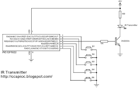
The following image shows the IR system transmitter circuit schematic diagram.
NEC IR remote control transmitter circuit PIC12F1822
In the circuit there 5 push buttons and each button sends a different IR signal code. The IR transmitter is the element that sends the IR signals to the IR receiver circuit.
The NPN transistor 2N2222 is used to drive the IR transmitter because the IR transmitter consumes high current and the microcontroller generally can't provide that amount of current.
PIC12F1822 internal pull-ups are enabled by the software and the internal oscillator is used as usual.
NEC Protocol IR transmitter (Encoder) using PIC12F1822 CCS PIC C code:
This is the full code of microcontroller of the NEC IR transmitter.
The NEC protocol carrier frequency is 38KHz and to generate this frequency PIC12F1822 CCP module is used as a PWM module. The floowing CCS C line is used to configure the PWM module:
#use pwm (PWM1, FREQUENCY = 38KHz, DUTY = 25, PWM_OFF)
The internal oscillator is used and set to 8MHz with PLL enabled (8 x 4 = 32MHz). The following line is used for that:
setup_oscillator(OSC_8MHZ | OSC_PLL_ON);
In the circuit there are 5 push buttons connected to RA0, RA1, RA3, RA4 and RA5 which means that pins must be configured as inputs and the PWM pin as output.
Internal pull-ups are enabled for the input pins with the following line:
port_a_pullups(0x3B);
The five buttons transmit the following signals respectively:
0x40BF00FF -- 0x40BF807F -- 0x40BF40BF -- 0x40BF20DF -- 0x40BFA05F
1s and 0s are transmitted as:
Transmit 1 : pwm_on();
Transmit 0: pwm_off();
For example the transmission of 9ms burst pulse and 4.5ms space:
// Send 9ms burst
pwm_on();
  delay_ms(9);
  // Send 4.5ms space
  pwm_off();
  delay_us(4500);

Full Code:
// Extended NEC protocol IR remote control transmitter CCS PIC C code
// http://ccspicc.blogspot.com/
// electronnote@gmail.com
// Use at your own risk

#include <12F1822.h>
#fuses NOMCLR INTRC_IO PLL_SW
#use delay(clock=32000000)
#use fast_io(A)
#use pwm (PWM1, FREQUENCY = 38KHz, DUTY = 25, PWM_OFF)

void send_signal(unsigned int32 number){
  int8 i;
  // Send 9ms burst
  pwm_on();
  delay_ms(9);
  // Send 4.5ms space
  pwm_off();
  delay_us(4500);
  // Send data
  for(i = 0; i < 32; i++){
    // If bit is 1 send 560us pulse and 1680us space
    if(bit_test(number, 31 - i)){
      pwm_on();
      delay_us(560);
      pwm_off();
      delay_us(1680);
    }
    // If bit is 0 send 560us pulse and 560us space
    else{
      pwm_on();
      delay_us(560);
      pwm_off();
      delay_us(560);
    }
  }
  // Send end bit
  pwm_on();
  delay_us(560);
  pwm_off();
  delay_us(560);
}
void main() {
  setup_oscillator(OSC_8MHZ | OSC_PLL_ON);            // Set internal oscillator to 32MHz (8MHz and PLL)
  output_a(0);
  set_tris_a(0x3B);                                   // Configure RA2 pin as output and others as inputs
  port_a_pullups(0x3B);                               // Enable internal pull-ups for pins RA0,RA1,RA3,RA4 & RA5
  while(TRUE){
    while(!input(PIN_A0)){
      send_signal(0x40BF00FF);
      delay_ms(500);
    }
    while(!input(PIN_A1)){
      send_signal(0x40BF807F);
      delay_ms(500);
    }
    while(!input(PIN_A3)){
      send_signal(0x40BF40BF);
      delay_ms(500);
    }
    while(!input(PIN_A4)){
      send_signal(0x40BF20DF);
      delay_ms(500);
    }
    while(!input(PIN_A5)){
      send_signal(0x40BFA05F);
      delay_ms(500);
    }
  }
}
NEC Protocol IR receiver (Decoder) using PIC12F1822:
The NEC receiver circuit schematic is shown below.
NEC IR remote control receiver circuit PIC12F1822
In the IR receiver circuit there are 5 LEDs and IR receiver. The IR receiver receives IR signals transmitted from the IR transmitter. Each LED is remotely controlled from one button in the transmitter circuit.
PIC12F1822 internal oscillator is used and MCLR pin is configured as a digital input pin.
NEC Protocol IR receiver (Decoder) using PIC12F1822 CCS PIC C code:
As in the IR transmitter the internal oscillator of the IR receiver microcontroller is used.
Timer1 is configured to increment every 1us and it is used to measure pulses spaces duration.
SETUP_TIMER_1(T1_INTERNAL | T1_DIV_BY_8);
For example to check the 9ms pulse the following lines are used:
// Check 9ms pulse (remote control sends logic high)
  SET_TIMER1(0);
  while(!input(IR_Sensor) && (count < 9500))
    count = GET_TIMER1();
  if( (count > 9499) || (count < 8500))
    return FALSE;

And checking the 4.5ms space as follows:
// Check 4.5ms space (remote control sends logic low)
  SET_TIMER1(0);
  count = 0;
  while((input(IR_Sensor)) && (count < 5000))
    count = GET_TIMER1();
  if( (count > 4999) || (count < 4000))
    return FALSE;

Full Code:
// Extended NEC protocol IR remote control decoder using PIC12F1822 CCS PIC C code
// http://ccspicc.blogspot.com/
// electronnote@gmail.com
// Use at your own risk

#include <12F1822.h>
#fuses NOMCLR INTRC_IO PLL_SW
#use delay(clock=32000000)
#use fast_io(A)
#define IR_Sensor PIN_A3

unsigned int32 ir_code;
short nec_remote_read(){
  unsigned int16 count = 0;
  unsigned int8 i;
  // Check 9ms pulse (remote control sends logic high)
  SET_TIMER1(0);
  while(!input(IR_Sensor) && (count < 9500))
    count = GET_TIMER1();
  if( (count > 9499) || (count < 8500))
    return FALSE;
  // Check 4.5ms space (remote control sends logic low)
  SET_TIMER1(0);
  count = 0;
  while((input(IR_Sensor)) && (count < 5000))
    count = GET_TIMER1();
  if( (count > 4999) || (count < 4000))
    return FALSE;
  // Read message (32 bits)
  for(i = 0; i < 32; i++){
    SET_TIMER1(0);
    count = 0;
    while(!input(IR_Sensor) && (count < 650))
      count = GET_TIMER1();
    if( (count > 649) || (count < 500))
      return FALSE;
    count = 0;
    SET_TIMER1(0);
    while((input(IR_Sensor)) && (count < 1800))
      count = GET_TIMER1();
    if( (count > 1799) || (count < 400))
      return FALSE;
    if( count > 1000)                                 // If space width > 1ms
      bit_set(ir_code, (31 - i));                     // Write 1 to bit (31 - i)
    else                                              // If space width < 1ms
      bit_clear(ir_code, (31 - i));                   // Write 0 to bit (31 - i)
  }
  return TRUE;
}
void main() {
  setup_oscillator(OSC_8MHZ | OSC_PLL_ON);            // Set internal oscillator to 32MHz (8MHz and PLL)
  output_a(0);
  set_tris_a(8);
  SETUP_TIMER_1(T1_INTERNAL | T1_DIV_BY_8);
  while(TRUE){
    while(input(IR_Sensor));                          // Wait until IR_Sensor pin falls
    if(nec_remote_read()){
      if(ir_code == 0x40BF00FF)
        output_toggle(PIN_A0);
      if(ir_code == 0x40BF807F)
        output_toggle(PIN_A1);
      if(ir_code == 0x40BF40BF)
        output_toggle(PIN_A2);
      if(ir_code == 0x40BF20DF)
        output_toggle(PIN_A4);
      if(ir_code == 0x40BFA05F)
        output_toggle(PIN_A5);
      }
  }
}
IR Remote control transmitter and receiver using PIC12F1822 microcontroller video:
The following video shows project final result.

Sunday, September 18, 2016

Extended NEC Protocol Decoder Using PIC12F1822 Microcontroller

NEC IR remote control decoder with PIC12F1822
This topic shows how to decode IR remote control uses extended NEC communication protocol.
The complete extended NEC protocol message is started by 9ms burst followed by 4.5ms space which is then followed by the Address and Command. The address is 16-bit length and the command is transmitted twice (8 bits + 8 bits) where in the second time all bits are inverted and can be used for verification of the received message. The following drawing shows an extended NEC message example.
Extended NEC protocol PIC12F1822
The NEC protocol uses pulse distance encoding of the bits. Each pulse is a 562.5µs long with carrier frequency of 38KHz. Logic bits are transmitted as follows:
Logic 0: 562.5µs pulse burst followed by a 562.5µs space, with a total transmit time of 1125µs (562.5 x 2).
Logic 1: a 562.5µs pulse burst followed by a 1687.5µs (562.5 x 3) space, with a total transmit time of 2250µs (562.5 x 4).
Extended NEC protocol decoder PIC12F1822
Extended NEC Protocol Decoder Using PIC12F1822:
Components List:
  •  PIC12F1822 Microcontroller
  • 1602 LCD
  • 10K Variable Resistor
  • 74HC595 Shift Register (74HC164, CD4094.....)
  • IR Receiver
  • 47µF Capacitor
  • 10K Resistor
  • +5V Power Supply
  • Protoboard
  • Jumper Wires
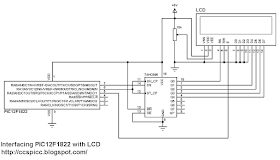
Extended NEC protocol decoder using PIC12F1822 circuit schematic is shown below where a 1602 LCD is used to display the NEC protocol parameters (address and command). To see how to interface this LCD with PIC12F1822 read the following topic:
Interfacing PIC12F1822 microcontroller with LCD display
Extended NEC protocol decoder IR remote control circuit schematic PIC12F1822
In this project PIC12F1822 microcontroller internal oscillator is used and MCLR pin is configured to work as a digital input.
By adding the shift register we can make a low coast 3-wire LCD.
A pull-up resistor (10KOhm) between VCC and the IR receiver output pin minimizes the noise on that pin.
To see how to use 74HC164 or CD4094 instead of 74HC595 read the topic at the link above.
Extended NEC Protocol Decoder CCS PIC C code:
PIC12F1822 microcontroller internal oscillator is set to 8MHz with PLL enabled which makes the microcontroller runs at 8 x 4 = 32MHz. The following line is used to deo that:
setup_oscillator(OSC_8MHZ | OSC_PLL_ON);
Timer1 is set to increment by 1 every 1us:
SETUP_TIMER_1(T1_INTERNAL | T1_DIV_BY_8);
Timer1 is used to measure pulses and spaces duration in us.
The extended NEC message code has a total of 32 bits which can be divided into 3 parts:
The first 16 bits are for address (address low and address high)
The next 8 bits for command and the last 8 bits for the inverted command.
Basically the microcontroller waits until the IR receiver receives an IR signal which makes its output change its state from high to low. This is done using the following line:
while(input(IR_Sensor));
Where IR_Sensor is the pin where the IR receiver output connected to.
After that a function named nec_remote_read() is called, this function checks if the received signal has NEC protocol form all the time and reads the message code bits.
if(nec_remote_read())
Timer1 is used to calculate pulses and space in microseconds. For example to check the 9ms burst the following lines are used:
SET_TIMER1(0);
  while(!input(IR_Sensor) && (count < 9500))
    count = GET_TIMER1();
  if( (count > 9499) || (count < 8500))
    return FALSE;

The variable count is used to store Timer1 value. An interval between 8500us and 9500us is used to check the 9ms burst (9000us).
The same thing is done for the 4.5ms space.
The complete CCS C code for the NEC decoder is as the one below.
// Extended NEC protocol IR remote control decoder using PIC12F1822 CCS PIC C code
// 3-Wire LCD driver must be added
// http://ccspicc.blogspot.com/
// electronnote@gmail.com
// Use at your own risk

//LCD module connections
#define LCD_DATA_PIN PIN_A0
#define LCD_CLOCK_PIN PIN_A1
#define LCD_EN_PIN PIN_A2
//End LCD module connections

#include <12F1822.h>
#fuses NOMCLR INTRC_IO PLL_SW
#use delay(clock=32000000)
#include <3WireLCD.c>
#use fast_io(A)
#define IR_Sensor PIN_A3

unsigned int32 ir_code;
unsigned int16 address;
unsigned int8 command, inv_command;
short nec_remote_read(){
  unsigned int16 count = 0;
  unsigned int8 i;
  // Check 9ms pulse (remote control sends logic high)
  SET_TIMER1(0);
  while(!input(IR_Sensor) && (count < 9500))
    count = GET_TIMER1();
  if( (count > 9499) || (count < 8500))
    return FALSE;
  // Check 4.5ms space (remote control sends logic low)
  SET_TIMER1(0);
  count = 0;
  while((input(IR_Sensor)) && (count < 5000))
    count = GET_TIMER1();
  if( (count > 4999) || (count < 4000))
    return FALSE;
  // Read message (32 bits)
  for(i = 0; i < 32; i++){
    SET_TIMER1(0);
    count = 0;
    while(!input(IR_Sensor) && (count < 650))
      count = GET_TIMER1();
    if( (count > 649) || (count < 500))
      return FALSE;
    count = 0;
    SET_TIMER1(0);
    while((input(IR_Sensor)) && (count < 1800))
      count = GET_TIMER1();
    if( (count > 1799) || (count < 400))
      return FALSE;
    if( count > 1000)                                 // If space width > 1ms
      bit_set(ir_code, (31 - i));                     // Write 1 to bit (31 - i)
    else                                              // If space width < 1ms
      bit_clear(ir_code, (31 - i));                   // Write 0 to bit (31 - i)
  }
  return TRUE;
}
void main() {
  setup_oscillator(OSC_8MHZ | OSC_PLL_ON);            // Set internal oscillator to 32MHz (8MHz and PLL)
  lcd_initialize();                                   // Initialize LCD module
  lcd_cmd(LCD_CLEAR);                                 // LCD Clear
  SETUP_TIMER_1(T1_INTERNAL | T1_DIV_BY_8);
  lcd_goto(1, 1);                                     // Go to column 1 line 1
  printf(lcd_out, "Address:0x0000");
  lcd_goto(1, 2);                                     // Go to column 1 line 2
  printf(lcd_out, "Com:0x00 In:0x00");
  while(TRUE){
    while(input(IR_Sensor));                          // Wait until IR_Sensor pin falls
    if(nec_remote_read()){
      address = ir_code >> 16;
      command = ir_code >> 8;
      inv_command = ir_code;
      lcd_goto(11, 1);                                // Go to column 11 line 1
      printf(lcd_out,"%4LX",address);
      lcd_goto(7, 2);                                 // Go to column 7 line 2
      printf(lcd_out,"%2X",command); 
      lcd_goto(15, 2);                                // Go to column 15 line 2
      printf(lcd_out,"%2X",inv_command);
      delay_ms(200);}
  }
}
NEC Protocol decoder with PIC12F1822 video:

Reference:
http://www.sbprojects.com/

Saturday, September 17, 2016

PIC12F1822 + LCD + DHT22 (AM2302) Sensor

Interfacing PIC12F1822 with DHT22 (AM2302) humidity and temperature sensor
After interfacing the microcontroller PIC12F1822 with DHT11 sensor at:
DHT11 Interfacing with PIC12F1822 microcontroller
Now let's see how to interface this microcontroller with DHT22 (AM2302) digital relative humidity and temperature sensor.
In order to understand this example please read the DHT22 (AM2302) datasheet.
To see how to simulate the DHT22 Proteus simulation and timing diagram read the following topic:
PIC16F877A and DHT22(AM2302, RHT03) sensor Proteus simulation
And the following topic shows how to interface LCD with PIC12F1822:
Interfacing PIC12F1822 microcontroller with LCD display
Required Components:
  • PIC12F1822 Microcontroller
  • LCD (1602 or 2004 or any compatible)
  • DHT22 (AM2302 - RHT03) Sensor
  • 74HC595 Shift Register (74HC164, CD4094....)
  • 10K Variable Resistor
  • 4.7K Resistor
  • +5V Power Supply
  • Breadboard
  • Jumper Wires
PIC12F1822 + LCD + DHT22 (AM2302) Sensor Circuit:
PIC12F1822 + LCD + DHT22 (AM2302 - RHT03) Sensor Circuit CCS
PIC12F1822 microcontroller internal oscillator is used and MCLR pin function is disabled in the software.
To see how to use 74HC164 or CD4094 instead of 74HC595 go to the link above.
The DHT22 (AM2302 - RHT03) sensor has 4 pins:
VCC : Positive power supply (+5V)
DATA : Sensor data input and output
NC : Not connected terminal
GND : Ground (0V)
A pull-up resistor must be added between the sensor data pin and VCC (+5V) pin as shown in the circuit schematic (4.7K ~ 10K).
PIC12F1822 + LCD + DHT22 (AM2302) Sensor CCS C code:
If you want to understand the code please read the DHT22 datasheet.
Variables Time_out and k are used to test reading time to avoid wrong data reception and microcontroller hanging.
The microcontroller runs with its internal oscillator at 32MHz (8MHz + PLL).
// Interfacing PIC12F1822 with DHT22 sensor CCS PIC C code
// 3-Wire LCD driver must be added
// http://ccspicc.blogspot.com/
// electronnote@gmail.com
// Use at your own risk

//LCD module connections
#define LCD_DATA_PIN PIN_A0
#define LCD_CLOCK_PIN PIN_A1
#define LCD_EN_PIN PIN_A2
//End LCD module connections

#include <12F1822.h>
#fuses NOMCLR INTRC_IO PLL_SW
#use delay(clock=32000000)
#include <3WireLCD.c>
#use fast_io(A)
#define DHT22_PIN PIN_A4                              // Connection pin between DHT22 and mcu

short Time_out;
char message1[] = "Temp = 00.0 C   ";
char message2[] = "RH   = 00.0 %   ";
unsigned int8 T_byte1, T_byte2, RH_byte1, RH_byte2, CheckSum ;
unsigned int16 Temp, RH;
void start_signal(){
  output_drive(DHT22_PIN);                            // Configure connection pin as output
  output_low(DHT22_PIN);                              // Connection pin output low
  delay_ms(25);
  output_high(DHT22_PIN);                             // Connection pin output high
  delay_us(30);
  output_float(DHT22_PIN);                            // Configure connection pin as input
}
short check_response(){
  delay_us(40);
  if(!input(DHT22_PIN)){                              // Read and test if connection pin is low
    delay_us(80);
    if(input(DHT22_PIN)){                             // Read and test if connection pin is high
      delay_us(50);
      return 1;
    }
  }
}
unsigned int8 Read_Data(){
  unsigned int8 i, k, _data = 0;                      // k is used to count 1 bit reading duration
  if(Time_out)
    break;
  for(i = 0; i < 8; i++){
    k = 0;
    while(!input(DHT22_PIN)){                         // Wait until DHT22 pin get raised
      k++;
      if(k > 100){
        Time_out = 1;
        break;
      }
      delay_us(1);
    }
    delay_us(30);
    if(!input(DHT22_PIN))
      bit_clear(_data, (7 - i));                      // Clear bit (7 - i)
    else{
      bit_set(_data, (7 - i));                        // Set bit (7 - i)
      while(input(DHT22_PIN)){                        // Wait until DHT22 pin goes low
        k++;
        if(k > 100){
        Time_out = 1;
        break;
      }
      delay_us(1);}
    }
  }
  return _data;
}
void main() {
  setup_oscillator(OSC_8MHZ | OSC_PLL_ON);            // Set internal oscillator to 32MHz (8MHz and PLL)
  lcd_initialize();                                   // Initialize LCD module
  lcd_cmd(LCD_CLEAR);                                 // LCD Clear
  while(TRUE){
    delay_ms(1000);
    Time_out = 0;
    Start_signal();
    if(check_response()){                             // If there is a response from sensor
      RH_byte1 = Read_Data();                         // read RH byte1
      RH_byte2 = Read_Data();                         // read RH byte2
      T_byte1 = Read_Data();                          // read T byte1
      T_byte2 = Read_Data();                          // read T byte2
      Checksum = Read_Data();                         // read checksum
      if(Time_out){                                   // If reading takes long time
        lcd_goto(1, 1);                               // Go to column 1 row 1
        lcd_out("    Time out!   ");
        lcd_goto(1, 2);                               // Go to column 1 row 2
        lcd_out("                ");                  // Clear 2nd row
      }
      else{
        if(CheckSum == ((RH_Byte1 + RH_Byte2 + T_Byte1 + T_Byte2) & 0xFF)){
          RH = RH_byte1;
          RH = (RH << 8) | RH_byte2;
          Temp = T_byte1;
          Temp = (Temp << 8) | T_byte2;
          if (Temp > 0X8000){
            message1[6] = '-';
            Temp = Temp & 0X7FFF; }
          else
            message1[6] = ' ';
          message1[7]  = (Temp / 100) % 10  + 48;
          message1[8]  = (Temp / 10) % 10  + 48;
          message1[10] = Temp % 10  + 48;
          message2[7]  = (RH / 100) % 10 + 48;
          message2[8]  = (RH / 10) % 10 + 48;
          message2[10] = RH % 10 + 48;
          message1[11] = 223;                         // Degree symbol    
          lcd_goto(1, 1);                             // Go to column 1 row 1
          printf(lcd_out, message1);                  // Display message1
          lcd_goto(1, 2);                             // Go to column 1 row 2
          printf(lcd_out, message2);                  // Display message2
        }
        else {
          lcd_goto(1, 1);                             // Go to column 1 row 1
          lcd_out("Checksum Error! ");
          lcd_goto(1, 2);                             // Go to column 1 row 2
          lcd_out("                ");                // Clear 2nd row
        }
      }
    }
    else {
      lcd_goto(1, 1);                                 // Go to column 1 row 1
      lcd_out("  No response   ");
      lcd_goto(1, 2);                                 // Go to column 1 row 2
      lcd_out("from the sensor ");
    }
  }
}
PIC12F1822 + LCD + DHT22 (AM2302) Sensor Video:


DHT11 Interfacing with PIC12F1822 microcontroller

In this blog there are some topics talking about the DHT11 relative humidity and temperature sensor and how to interface it with different types of PIC microcontrollers. The datasheet of the DHT11 sensor shows its characteristics and how it works.
Also the following topic shows the DHT11 timing and how to simulate it using Proteus:
Interfacing PIC16F877A with DHT11 (RHT01) sensor Proteus simulation
This topic shows how to interface this sensor with the microcontroller PIC12F1822. This microcontroller has only 8 pins and 6 of them can work as an I/O pins.
An LCD is used to display temperature and relative humidity values. A shift register is used to make a 3-wire LCD as shown at the following link;
Interfacing PIC12F1822 microcontroller with LCD display
Therefor for this simple project we need 3 data lines for the LCD and 1 line for the DHT11 sensor which means we need 4 I/O pins.
Components List:
  • PIC12F1822 Microcontroller
  • DHT11 (RHT01) Sensor
  • 1602 LCD
  • 74HC595 Shift Register (74HC164 or CD4094 can do the job)
  • 10K Variable Resistor
  • 4.7K Resistor
  • +5V Power Supply
  • Breadboard
  • Jumper Wires
Interfacing PIC12F1822 with DHT11 sensor circuit:
Interfacing PIC12F1822 with DHT11 (RHT01) sensor circuit CCS C
The shift register data line is connected to RA0 pin and the clock line is connected to RA1 pin. LCDs enable pin is connected to pin RA3.
The internal oscillator of the PIC12F1822 microcontroller is used.
To see how to use 74HC164 or CD4094 instead of 74HC595 go to the link above.
The DHT11 sensor has 4 pins:
VCC : Positive power supply (+5V)
DATA : Sensor data input and output
NC : Not connected terminal
GND : Ground (0V)
A pull-up resistor must be added between the DHT11 data pin and VCC (+5V) pin as shown in the circuit schematic (4.7K ~ 10K).
Interfacing PIC12F1822 with DHT11 sensor CCS C code:
If you want to understand the code please read the DHT11 datasheet.
Variables Time_out and k are used to test reading time to avoid wrong data reception and microcontroller hanging.
The microcontroller runs with its internal oscillator at 32MHz (8MHz + PLL).
// Interfacing PIC12F1822 with DHT11 sensor CCS PIC C code
// 3-Wire LCD driver must be added
// http://ccspicc.blogspot.com/
// electronnote@gmail.com
// Use at your own risk

//LCD module connections
#define LCD_DATA_PIN PIN_A0
#define LCD_CLOCK_PIN PIN_A1
#define LCD_EN_PIN PIN_A2
//End LCD module connections

#include <12F1822.h>
#fuses NOMCLR INTRC_IO PLL_SW
#use delay(clock=32000000)
#include <3WireLCD.c>
#use fast_io(A)
#define DHT11_PIN PIN_A4                              // Connection pin between DHT11 and mcu

char message1[] = "Temp = 00.0 C  ";
char message2[] = "RH   = 00.0 %  ";
short Time_out;
unsigned int8 T_byte1, T_byte2, RH_byte1, RH_byte2, CheckSum ;
void start_signal(){
  output_drive(DHT11_PIN);                            // Configure connection pin as output
  output_low(DHT11_PIN);                              // Connection pin output low
  delay_ms(25);
  output_high(DHT11_PIN);                             // Connection pin output high
  delay_us(30);
  output_float(DHT11_PIN);                            // Configure connection pin as input
}
short check_response(){
  delay_us(40);
  if(!input(DHT11_PIN)){                              // Read and test if connection pin is low
    delay_us(80);
    if(input(DHT11_PIN)){                             // Read and test if connection pin is high
      delay_us(50);
      return 1;
    }
  }
}
unsigned int8 Read_Data(){
  unsigned int8 i, k, _data = 0;                      // k is used to count 1 bit reading duration
  if(Time_out)
    break;
  for(i = 0; i < 8; i++){
    k = 0;
    while(!input(DHT11_PIN)){                         // Wait until DHT11 pin get raised
      k++;
      if(k > 100){
        Time_out = 1;
        break;
      }
      delay_us(1);
    }
    delay_us(30);
    if(!input(DHT11_PIN))
      bit_clear(_data, (7 - i));                      // Clear bit (7 - i)
    else{
      bit_set(_data, (7 - i));                        // Set bit (7 - i)
      while(input(DHT11_PIN)){                        // Wait until DHT11 pin goes low
        k++;
        if(k > 100){
        Time_out = 1;
        break;
      }
      delay_us(1);}
    }
  }
  return _data;
}
void main() {
  setup_oscillator(OSC_8MHZ | OSC_PLL_ON);            // Set internal oscillator to 32MHz (8MHz and PLL)
  lcd_initialize();                                   // Initialize LCD module
  lcd_cmd(LCD_CLEAR);                                 // LCD Clear
  delay_ms(1000);
  while(TRUE){
    Time_out = 0;
    Start_signal();
    if(check_response()){                             // If there is a response from sensor
      RH_byte1 = Read_Data();                         // read RH byte1
      RH_byte2 = Read_Data();                         // read RH byte2
      T_byte1 = Read_Data();                          // read T byte1
      T_byte2 = Read_Data();                          // read T byte2
      Checksum = Read_Data();                         // read checksum
      if(Time_out){                                   // If reading takes long time
        lcd_cmd(LCD_CLEAR);                           // LCD Clear
        lcd_goto(5, 1);                               // Go to column 5 row 1
        lcd_out("Time out!");
      }
      else{
       if(CheckSum == ((RH_Byte1 + RH_Byte2 + T_Byte1 + T_Byte2) & 0xFF)){
         message1[7]  = T_Byte1/10  + 48;
         message1[8]  = T_Byte1%10  + 48;
         message1[10] = T_Byte2/10  + 48;
         message2[7]  = RH_Byte1/10 + 48;
         message2[8]  = RH_Byte1%10 + 48;
         message2[10] = RH_Byte2/10 + 48;
         message1[11] = 223;                          // Degree symbol
         lcd_goto(1, 1);                              // Go to column 1 row 1
         printf(lcd_out, message1);                   // Display message1
         lcd_goto(1, 2);                              // Go to column 1 row 2
         printf(lcd_out, message2);                   // Display message2
       }
       else{
         lcd_cmd(LCD_CLEAR);                          // LCD Clear
         lcd_goto(1, 1);                              // Go to column 1 row 1
         lcd_out("Checksum Error!");
       }
      }
    }
    else {
      lcd_cmd(LCD_CLEAR);                             // LCD Clear
      lcd_goto(3, 1);                                 // Go to column 3 row 1
      lcd_out("No response");
      lcd_goto(1, 2);                                 // Go to column 1 row 2
      lcd_out("from the sensor");
    }
  delay_ms(1000);
  }
}
Interfacing PIC12F1822 with DHT11 video:

Friday, September 16, 2016

Interfacing PIC12F1822 microcontroller with LCD display

PIC12F1822 LCD Example using CCS PIC C compiler with one line scrolling
This topic shows how to interface the microcontroller PIC12F1822 with LCD display (1602, 2004 .....) using CCS C compiler.
The microcontroller PIC12F1822 has only 8 pins and only 5 of them can be configured as outputs. The LCD display needs at least 6 data lines to operate and we can not connect it directly to PIC12F1822 microcontroller.
Using a serial in parallel out shift register (74HC595, 74HC164, CD4094 ......) we can minimize the number of pins used by the LCD to 3.
Using the 3-wire LCD driver of the CCS C compiler we can easily interface the PIC12F1822 with LCD display. The 3-wire LCD driver can be found at:
3-Wire LCD driver for CCS PIC C compiler
It is easy to add this driver to your project just download the C file and copy it to your project folder or to the CCS PIC C driver folder.
Components list:
  • PIC12F1822 Microcontroller
  • LCD Display with HD44780 or compatible controller
  • 74HC595 Shift Register (74HC164 or CD4094 can be used)
  • 10K Variable Resistor
  • +5V Power Supply
  • Breadboard
  • Jumper Wires
Interfacing PIC12F1822 microcontroller with LCD display circuit:
Interfacing PIC12F1822 with LCD 74HC595 shift register circuit
The shift register data line is connected to RA0 pin and the clock line is connected to RA1 pin. LCDs enable pin is connected to pin RA3.
The internal oscillator of the PIC12F1822 microcontroller is used.
To see how to use 74HC164 or CD4094 instead of 74HC595 see the 3-wire LCD driver topic at the link above.
Interfacing PIC12F1822 microcontroller with LCD display CCS C code:
This is the full code of this example where the microcontroller runs with its internal oscillator at 32MHz. The code shows how to make only one line scrolling as shown in the video below.
// Interfacing PIC12F1822 with LCD display CCS PIC C code
// 3-Wire LCD driver must be added
// http://ccspicc.blogspot.com/
// electronnote@gmail.com
// Use at your own risk

//LCD module connections
#define LCD_DATA_PIN PIN_A0
#define LCD_CLOCK_PIN PIN_A1
#define LCD_EN_PIN PIN_A2
//End LCD module connections

#include <12F1822.h>
#fuses NOMCLR INTRC_IO PLL_SW
#use delay(clock=32000000)
#include <3WireLCD.c>

unsigned int8 i;
char message[] = "PIC12F1822 LCD Example ";
void main() {
  setup_oscillator(OSC_8MHZ | OSC_PLL_ON);    // Set internal oscillator to 32MHz
  lcd_initialize();                           // Initialize LCD module
  lcd_cmd(LCD_CLEAR);                         // Clear the LCD
  lcd_goto(3, 1);                             // Go to column 3 line 1
  lcd_out("Hello world!");
  // Scroll 2nd line only
  for(i = 17; i > 0; i--){
    lcd_goto(i, 2);
    printf(lcd_out, message);
    delay_ms(200);
  }
  for(i = 0; i < 23; i++){
    lcd_goto(1, 2);
    printf(lcd_out, message + i);
    delay_ms(200);
  }
  // End scrolling 2nd line
  delay_ms(2000);
  lcd_goto(4, 2);                             // Go to column 4 line 2
  lcd_out("3-Wire LCD");
  delay_ms(2000);
  lcd_goto(4, 2);                             // Go to column 4 line 2
  lcd_out("          ");                      // Clear 2nd line
  i = 0;
  while(TRUE){
    for(i = 0; i < 200; i++){
      lcd_goto(7, 2);                           // Go to column 7 row 4
      printf(lcd_out,"%3u",i);                  // Write i with 3 numbers max
      delay_ms(500);
    }
  }
}                                                // End of program

PIC12F1822  LCD Example Video:

Thursday, September 15, 2016

USB Mouse using PIC18F4550 microcontroller

PIC18F4550 microcontroller has USB module which can work as a HID (Human Interface Device). The USB HID device doesn't need any additional driver because it's already installed in most of modern operating systems.
Using PIC18F4550 as a HID device we can easily transfer data between PC and the microcontroller as shown at the following URL:
PIC18F4550 USB HID Example using CCS PIC C
This topic shows how to build a simple USB HID mouse using PIC18F4550 microcontroller (PIC18F2550 can also be used).
Required Components:
  • PIC18F4550 Microcontroller ( or PIC18F2550) 
  • 8MHz Crystal Oscillator
  • 2 x 22pF capacitors
  • 470nF Capacitor
  • 6 Push-Buttons
  • USB Connector
  • +5V Power Supply (USB VCC can be used)
  • Protoboard
  • Jumper Wires
Project circuit schematic is shown below:
PIC18F4550 PIC18F2550 USB HID Mouse circuit
USB Mouse using PIC18F4550 CCS C code:
The CCS PIC C compiler has USB Mouse driver which allows us to build a USB mouse more easily. The following line is used to add this driver to this project:
#include <usb_desc_mouse.h>
In this project there is no need to receive data from the HID device, we have only to send data to this device using the following line:
usb_put_packet(1, out_data, 4, USB_DTS_TOGGLE);
Where out_data is an array of 4 elements (4 bytes):
Byte 1 corresponds to button status. The left button of the mouse is represented by 0x01 and the right button is represented by 0x03.
Byte 2 and byte 3 correspond to X axis and Y axis directions.
Byte 4 for the mouse wheel which is not used in this project.
The X axis and Y axis bytes are signed int8 which can vary from -127 to 127. The ( - ) sign indicates direction ( for X axis left/right and for Y axis up/down) and the number means number of steps at a time.
The complete C code is as the one below:
// PIC18F4550 USB Mouse CCS C code
// http://ccspicc.blogspot.com/
// electronnote@gmail.com
// Use at your own risk

#include <18F4550.h>
#fuses  HSPLL PLL2 CPUDIV1 USBDIV VREGEN NOMCLR
#use delay(clock = 48000000)
#include <usb_desc_mouse.h>
#include<pic18_usb.h>
#include<usb.c>
#use fast_io(B)

char out_data[4];
void main(){
  setup_adc_ports(NO_ANALOGS);                          // Configure all AN pins as digital
  output_b(0);                                          // PORTB initial state
  set_tris_b(0x3F);                                     // Configure RB0 to RB5 as inputs
  port_b_pullups(TRUE);                                 // Enable PORTB pull-ups
  usb_init_cs();                                        // Initialize USB hardware
  delay_ms(1000);
  while(TRUE){
    usb_task();
    if(usb_enumerated()){                               // If the device has been enumerated by the PC
      while(!input(PIN_B0)){
        out_data[0] = 0;
        out_data[1] = 1;
        out_data[2] = 0;
        out_data[3] = 0;
        usb_put_packet(1,out_data,4,USB_DTS_TOGGLE);
      }
      while(!input(PIN_B1)){
        out_data[0] = 0;
        out_data[1] = -1;
        out_data[2] = 0;
        out_data[3] = 0;
        usb_put_packet(1,out_data,4,USB_DTS_TOGGLE);
      }
      while(!input(PIN_B2)){
        out_data[0] = 0;
        out_data[1] = 0;
        out_data[2] = 1;
        out_data[3] = 0;
        usb_put_packet(1,out_data,4,USB_DTS_TOGGLE);
      }
      while(!input(PIN_B3)){
        out_data[0] = 0;
        out_data[1] = 0;
        out_data[2] = -1;
        out_data[3] = 0;
        usb_put_packet(1, out_data, 4, USB_DTS_TOGGLE);
      }
      while(!input(PIN_B4)){
        out_data[0] = 1;
        out_data[1] = 0;
        out_data[2] = 0;
        out_data[3] = 0;
        usb_put_packet(1,out_data,4,USB_DTS_TOGGLE);
      }
      while(!input(PIN_B5)){
        while(!input(PIN_B5));
        out_data[0] = 3;
        out_data[1] = 0;
        out_data[2] = 0;
        out_data[3] = 0;
        usb_put_packet(1,out_data,4,USB_DTS_TOGGLE);
      }
        out_data[0] = 0;
        out_data[1] = 0;
        out_data[2] = 0;
        out_data[3] = 0;
        usb_put_packet(1,out_data,4,USB_DTS_TOGGLE);
    }
  }
}
USB Mouse using PIC18F4550 video:
This video shows a simple hardware circuit connected to PC where the screen is divided into two parts, the left part is a recorded video of the PC screen and the right side shows the hardware circuit.