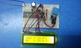
In this post I'm not going to give any details about the DHT11 sensor because every thing is in the datasheet of the device which can be downloaded from the following link:
DHT11 Datasheet Download
Hardware Required:
- PIC16F887 Microcontroller
- DHT11 Sensor
- 1602 LCD screen
- 10K Potentiometer
- 4.7K ohm resistor
- 0.1µF Ceramic capacitor (Optional but recommended)
- +5V Power source
- Breadboards
- Jumper wires
Project circuit diagram is below.
The internal oscillator of the microcontroller is used and MCLR pin function is disabled.
Interfacing PIC16F887 with DHT11 sensor CCS C code:
Reading the datasheet of the DHT11 sensor is recommended for understanding the source code.
/* Interfacing PIC16F887 with DHT11 sensor CCS C code
   Read DHT11 datasheet to understand the code!
   Internal oscillator used @ 8MHz
   Timer1 is configured so that it increments every 1µs
   http://ccspicc.blogspot.com/
   electronnote@gmail.com
*/

//LCD module connections
#define LCD_RS_PIN PIN_D0
#define LCD_RW_PIN PIN_D1
#define LCD_ENABLE_PIN PIN_D2
#define LCD_DATA4 PIN_D3
#define LCD_DATA5 PIN_D4
#define LCD_DATA6 PIN_D5
#define LCD_DATA7 PIN_D6
//End LCD module connections

#include <16F887.h>
#fuses NOMCLR NOBROWNOUT NOLVP INTRC_IO
#use delay(clock = 8MHz)
#include <lcd.c>
#use fast_io(B)
#use fast_io(D)
#define DHT11_PIN PIN_B0                              // DHT11 Data pin is connected to RB0

char message1[] = "Temp = 00.0 C  ";
char message2[] = "RH   = 00.0 %  ";
short Time_out = 0;
unsigned int8 T_byte1, T_byte2, RH_byte1, RH_byte2, CheckSum ;
void start_signal(){
  output_drive(DHT11_PIN);                            // Configure connection pin as output
  output_low(DHT11_PIN);                              // Connection pin output low
  delay_ms(25);
  output_high(DHT11_PIN);                             // Connection pin output high
  delay_us(25);
  output_float(DHT11_PIN);                            // Configure connection pin as input
}
short check_response(){
  set_timer1(0);                                      // Set Timer1 value to 0
  setup_timer_1(T1_INTERNAL | T1_DIV_BY_2);           // Start Timer1 with internal clock source + 2 prescaler
  while(!input(DHT11_PIN) && get_timer1() < 100);     // Wait until DHT11_PIN becomes high (cheking of 80µs low time response)
  if(get_timer1() > 99)                               // If response time > 99µS  ==> Response error
    return 0;                                         // Return 0 (Device has a problem with response)
  else{
    set_timer1(0);                                    // Set Timer1 value to 0
    while(input(DHT11_PIN) && get_timer1() < 100);    // Wait until DHT11_PIN becomes low (cheking of 80µs high time response)
    if(get_timer1() > 99)                             // If response time > 99µS  ==> Response error
      return 0;                                       // Return 0 (Device has a problem with response)
    else
      return 1;                                       // Return 1 (response OK)
  }
}
unsigned int8 Read_Data(){
  unsigned int8 i, _data = 0;
  if(Time_out)
    break;
  for(i = 0; i < 8; i++){
    set_timer1(0);                                    // Set Timer1 value to 0
    while(!input(DHT11_PIN))                          // Wait until DHT11_PIN becomes high
      if(get_timer1() > 100){                         // If low time > 100  ==>  Time out error (Normally it takes 50µs)
        Time_out = 1;
        break;
      }
    set_timer1(0);                                    // Set Timer1 value to 0
    while(input(DHT11_PIN))                           // Wait until DHT11_PIN becomes low
      if(get_timer1() > 100){                         // If high time > 100  ==>  Time out error (Normally it takes 26-28µs for 0 and 70µs for 1)
        Time_out = 1;
        break;
      }
     if(get_timer1() > 50)                            // If high time > 50  ==>  Sensor sent 1
       bit_set(_data, (7 - i));                       // Set bit (7 - i)
  }
  return _data;
}
void main(){
  setup_oscillator(OSC_8MHZ);                         // Set the internal oscillator to 8MHz
  setup_timer_1(T1_DISABLED);                         // Disable Timer1
  lcd_init();                                         // Initialize LCD module
  lcd_putc('\f');                                     // Clear LCD
  while(TRUE){
    delay_ms(1000);                                   // Wait 1s
    Time_out = 0;
    Start_signal();                                   // Send start signal to the sensor
    if(check_response()){                             // Check if there is a response from sensor (If OK start reding humidity and temperature data)
      RH_byte1 = Read_Data();                         // read RH byte1
      RH_byte2 = Read_Data();                         // read RH byte2
      T_byte1  = Read_Data();                         // read T byte1
      T_byte2  = Read_Data();                         // read T byte2
      Checksum = Read_Data();                         // read checksum
      setup_timer_1(T1_DISABLED);                     // Disable Timer1
      if(Time_out) {                                  // If there is a time out in reading
        lcd_putc('\f');                               // LCD clear
        lcd_gotoxy(5, 1);                             // Go to column 5 row 1
        lcd_putc("Time out!");                        // Display "Time out!"
      }
      else {                                          // If there is no time out
        if(CheckSum == ((RH_Byte1 + RH_Byte2 + T_Byte1 + T_Byte2) & 0xFF)){
          message1[7]  = T_Byte1/10  + 48;
          message1[8]  = T_Byte1%10  + 48;
          message1[10] = T_Byte2/10  + 48;
          message2[7]  = RH_Byte1/10 + 48;
          message2[8]  = RH_Byte1%10 + 48;
          message2[10] = RH_Byte2/10 + 48;
          message1[11] = 223;                         // Degree symbol
          lcd_gotoxy(1, 1);                           // Go to column 1 row 1
          printf(lcd_putc, message1);                 // Display message1
          lcd_gotoxy(1, 2);                           // Go to column 1 row 2
          printf(lcd_putc, message2);                 // Display message2
        }
        else {
          lcd_putc('\f');                             // LCD clear
          lcd_gotoxy(1, 1);                           // Go to column 1 row 1
          lcd_putc("Checksum Error!");
        }
      }
    }
    else {                                            // If there is no response from DHT11
      lcd_putc('\f');                                 // LCD clear
      lcd_gotoxy(3, 1);                               // Go to column 3 row 1
      lcd_putc("No response");
      lcd_gotoxy(1, 2);                               // Go to column 1 row 2
      lcd_putc("from the sensor");
    }
  }
}
DHT11 With PIC16F887 microcontroller simulation video:
Source code, hex and Proteus simulation files can be downloaded from the following link.
Download

