BLDC Motor controller using PIC18F4550 and L293D
In the following topic URL we've seen how to control BLDC motor speed and direction of rotation using PIC18F4550 microcontroller and 3-phase bridge circuit:CD-ROM Spindle motor (BLDC) control with PIC18F4550 microcontroller
This topic shows how to make the same controller using L293D motor driver instead of the 3-phase bridge circuit.
The 3 phase bridge is more complicated and expansive and while the L293D motor driver chip is a small, cheap and saves time.
In this project we need two L293D chips because the BLDC motor is a three phase motor, and at any time two windings energized while the third one floating.
The L293D has 4 inputs and 4 outputs with 2 enable pins, each enable pin controls 2 outputs as shown below:
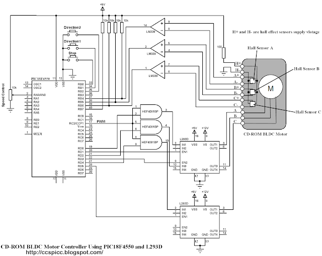
Complete circuit schematic is shown below:
In the circuit there are 3 buttons connected to RB0, RB1 and RB2. The buttons connected to RB1 and RB2 are used to start the BLDC motor and the other button is a stop button.
The BLDC motor speed is controlled using a potentiometer connected to AN0 channel.
There are 3 AND gates (HEF4081BP) in the circuit, these gates are used to get a 3 PWM signals from the original one which comes from RC2 pin using CCP1 module.
HEF4081BP has 4 independent 2-input AND gates, three of them are used. This IC needs a supply voltage of +5V between pins 7 (GND) and 14 (VCC).
PIC18F4550 microcontroller internal oscillator is used (8MHz).
BLDC Motor control using PIC18F4550 and L293D CCS PIC C code:
// Sensored BLDC motor controller using PIC18F4550 and L293D CCS C code
// http://ccspicc.blogspot.com/
// electronnote@gmail.com

#include <18F4550.h>
#device ADC = 10
#fuses NOMCLR INTRC_IO
#use delay(clock = 8000000)
#use fast_io(B)
#use fast_io(D)

int8 hall, Direction = 0;
int8 MoveTable1[8] = {0, 50, 11, 56, 44, 14, 35, 0};
int8 MoveTable2[8] = {0, 35, 14, 44, 56, 11, 50, 0};
#INT_RB                                       // RB port interrupt on change
void rb_isr(void){
  hall = (input_b() >> 4) & 7;
  if(Direction == 1)
    output_d(MoveTable1[hall]);
  else
    output_d(MoveTable2[hall]);
  clear_interrupt(INT_RB);
}
void main(){
  setup_oscillator(OSC_8MHZ);                 // Set internal oscillator to 8MHz
  setup_adc_ports(AN0);                       // Configure RA0 (AN0) pin as analog
  output_b(0);                                // PORTB initial state
  set_tris_b(0xF7);                           // TRISB configurartion
  port_b_pullups(TRUE);                       // Enable PORTB internal pull-ups
  output_d(0);                                // PORTD initial state
  set_tris_d(0);                              // Configure PORTD pins as outputs
  setup_adc(ADC_CLOCK_DIV_8);                 // Set ADC conversion time to 64Tosc
  set_adc_channel(0);                         // Select channel 0 input
  setup_timer_2(T2_DIV_BY_1, 199, 1);         // Timer2 configuration for PWM
  setup_ccp1(CCP_OFF);
  enable_interrupts(GLOBAL);                  // Enable global interrupts
  while(TRUE){
    if(!input(PIN_B1)){                       // If RB1 button pressed
      if(Direction == 0){
        Direction = 1;
        setup_ccp1(CCP_PWM);                  // Configure CCP1 as a PWM
        clear_interrupt(INT_RB);              // Clear RB IOC flag bit
        enable_interrupts(INT_RB);            // Enable PORTB IOC
        hall = (input_b() >> 4) & 7;
        output_d(MoveTable1[hall]);
      }
    }
    if(!input(PIN_B2)){                       // If RB1 button pressed
      if(Direction == 0){
        Direction = 2;
        setup_ccp1(CCP_PWM);                  // Configure CCP1 as a PWM
        clear_interrupt(INT_RB);              // Clear RB IOC flag bit
        enable_interrupts(INT_RB);            // Enable PORTB IOC
        hall = (input_b() >> 4) & 7;
        output_d(MoveTable2[hall]);
      }
    }
    while(Direction != 0){
     set_pwm1_duty(read_adc());
     if(!input(PIN_B0)){
       disable_interrupts(INT_RB);             // Disable PORTB IOC
       output_d(0);
       setup_ccp1(CCP_OFF);                    // CCP1 OFF
       Direction = 0;
     }
   }
  }
}
BLDC Motor controller using PIC18F4550 and L293D video:
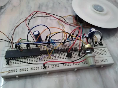
The following video shows project hardware circuit.
References:
Microchip: Sensored BLDC Motor Control Using dsPIC30F2010 (AN957).
Microchip: Brushless DC Motor Control Made Easy (AN857).
L293D Datasheet.


