Sunday, August 28, 2016

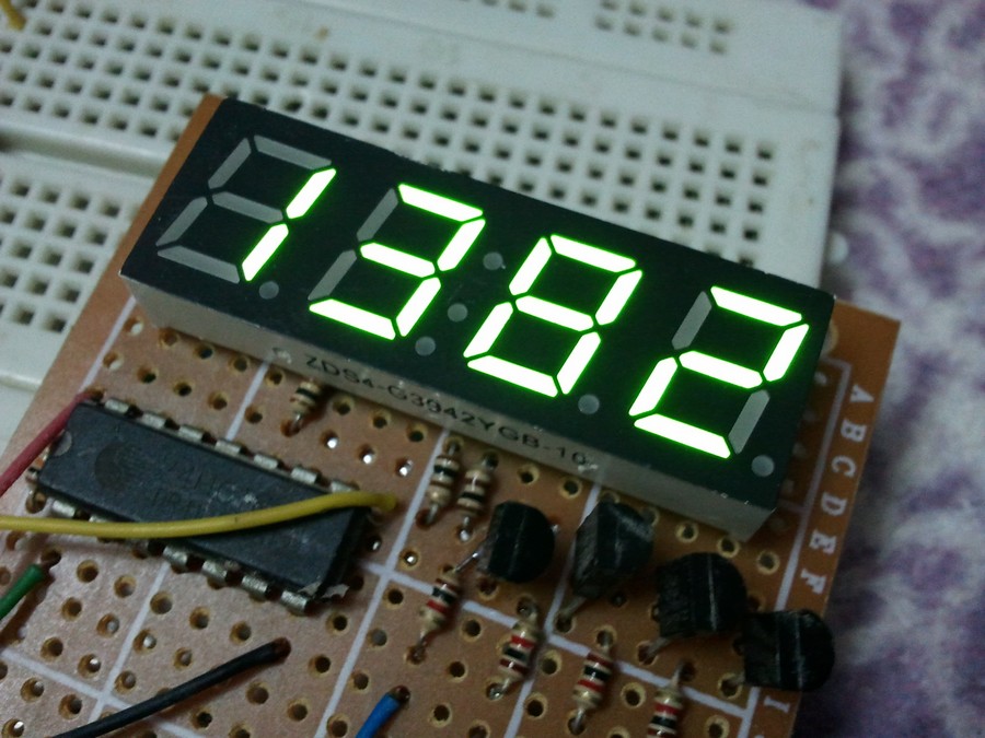
4-Digit 7-Segment display with 74HC595 shift register


Digital up/down counter using 7 segment display with multiplexing and 74HC595 and PIC16F877A circuit 
There are many topics in this blog talking about the 7-segment display and how to interface it with different types of PIC microcontrollers. One of these topics shows how to interface PIC16F877A with a multiplexed 4-digit 7-segment display with the shift register 74HC164N.
In this topic we are going to see how to make a digital up/down counter using multiplexed 7-segment display with 74HC595 shift register and PIC16F877A microcontroller.
From the 74HC595 datasheet this shift register is a high speed, 8-stage serial shift register with a storage register and 3-state outputs. The registers have separate clocks.
Data is shifted on the positive-going transitions of the shift register clock input (SHCP). The data in each register is transferred to the storage register on a positive-going transition of the storage register clock input (STCP). If both clocks are connected together, the shift register will always be one clock pulse ahead of the storage register.
The following table shows the 74HC595 shift register pin-outs:
74HC595 Shift register pin outs
7-Segment display with 74HC595 shift register:
The following circuit schematic shows a multiplexed 4 digits connected to the 74HC595 shift register. The type of the 7-segment display used in this example is common anode.
In the circuit there are two push buttons, these buttons are used to increment and decrement the displayed number.
7-Segment display with 74HC595 shift register interfacing with PIC16F877A circuit CCS PIC C
7-Segment display with 74HC595 shift register interfacing with PIC16F877A CCS C code:
Here is the example code I think it is a small and clear code.
// 4-Digit 7-Segment display with 74HC595 interfacing with PIC16F877A CCS C code
// http://ccspicc.blogspot.com/
// electronnote@gmail.com

#define data_pin PIN_B0
#define clock_pin PIN_B1
#define latch_pin PIN_B2
#include <16F877A.h>
#fuses HS,NOWDT,NOPROTECT,NOLVP
#use delay(clock = 8000000)
#use fast_io(B)
#use fast_io(D)

short s;                                   // Used to know buttons position
unsigned int j, digit ;
unsigned long i = 0;
unsigned int seg(unsigned int num) {
  switch (num) {
    case 0 : return 0x80;
    case 1 : return 0xF2;
    case 2 : return 0x48;
    case 3 : return 0x60;
    case 4 : return 0x32;
    case 5 : return 0x24;
    case 6 : return 0x04;
    case 7 : return 0xF0;
    case 8 : return 0;
    case 9 : return 0x20;
    }
}
void write_data(unsigned int number){
  for(j = 0x80; j > 0; j = j >> 1) {
     if(number & j)
       output_high(data_pin);
     else
       output_low(data_pin);
     output_high(clock_pin);
     output_low(clock_pin);
   }
     output_high(latch_pin);
     output_low(latch_pin);
}
void main(){
  port_b_pullups(TRUE);                  // Enable PORTB pull-ups
  output_b(0);                           // PORTB initial state
  set_tris_b(0x18);                      // Configure RB3 & RB4 pins as inputs
  output_d(0);                           // PORTD initial state
  set_tris_d(0);                         // Configure PORTD pins as inputs
  while(TRUE){
    if(input(PIN_B3) && input(PIN_B4))
      s = 1;
    if(s == 1) {
      if(input(PIN_B3) == 0) {
       s = 0;
       i++;
       if(i > 9999)
         i = 0;
      }
      if(input(PIN_B4) == 0) {
       s = 0;
       if(i < 1)
         i = 1;
       i--;
      }
    }
    digit = seg(i % 10);                 // Prepare to display ones
    output_d(0x0F);                      // Turn off all displays
    write_data(digit);
    output_d(0x07);                      // Turn on display for ones
    delay_ms(1);
    digit = seg((i / 10) % 10);          // Prepare to display tens
    output_d(0x0F);                      // Turn off all displays
    write_data(digit);
    output_d(0x0B);                      // Turn on display for tens
    delay_ms(1);
    digit = seg((i / 100) % 10);         // Prepare to display hundreds
    output_d(0x0F);                      // Turn off all displays
    write_data(digit);
    output_d(0x0D);                      // Turn on display for hundreds
    delay_ms(1);
    digit = seg((i / 1000) % 10);        // Prepare to display thousands
    output_d(0x0F);                      // Turn off all displays
    write_data(digit);
    output_d(0x0E);                      // Turn on display for thousands
    delay_ms(1);
  }
}

7-Segment display with 74HC595 shift register interfacing with PIC16F877A video:
The following video from a real hardware circuit for the digital counter.
Saturday, March 19, 2016

Interfacing 7-segment display with PIC12F1822 using CCS PIC C compiler


Three-digit counter using PIC12F1822 and CCS C
7 segment pic microcontroller ccs pic c 
The easiest way to interface 7-segment display with PIC12F1822 microcontroller is to add a serial-in parallel-out shift register. The adding of the shift register minimizes the number of pins used by the 7-segment display. This topic shows how to make a 3-digit digital counter with multiplexing and 74HC164 shift register using PIC16F877A and CCS PIC C compiler.
Interfacing PIC12F1822 with 7-segment display circuit:
Here is an example shows how to make a digital up counter where the number is displayed on a 7 segment display uses multiplexing technique with shift register.
Example circuit schematic is shown below where a common anode 7-segment display and 74HC164N shift register are used.
Other shift registers such as 74HC595 or CD4094 can be used in this project.
The displayed number can be incremented using the button which is connected to RA3 pin.
pic12f1822 7 segment shift register ccs pic c
Internal oscillator of the microcontroller is used @ 8MHz and MCLR pin function is disabled.
The push button is connected to RA3 pin. The shift register used is 74HC164 but other types can work properly like 74HC595 or CD4094.
In this example all pins of PIC12F1822 are used and there is no free pin.
Interfacing PIC12F1822 with 7-segment display CCS C code:

// Interfacing PIC12F1822 with 7-segment display
// Common anode 7-segment display used
// http://ccspicc.blogspot.com/
// electronnote@gmail.com

#include <12F1822.h>
#fuses NOMCLR INTRC_IO
#use delay(clock=8000000)
#use fast_io (a)


short s;   // Used to know button position
unsigned int j, digit, digit1, digit10, digit100;
unsigned long i = 0;
unsigned int seg(unsigned int num) {
  switch (num) {
    case 0 : return 0xC0;
    case 1 : return 0xF9;
    case 2 : return 0xA4;
    case 3 : return 0xB0;
    case 4 : return 0x99;
    case 5 : return 0x92;
    case 6 : return 0x82;
    case 7 : return 0xF8;
    case 8 : return 0x80;
    case 9 : return 0x90;
   }
}
void main() {
  setup_oscillator(OSC_8MHZ);          // Set internal oscillator to 8MHz
  set_tris_a(8);                       // Configure RA3 pin as input
  port_a_pullups(8);                   // Enable RA3 internal pull-up
  while(TRUE) {
   if(input(PIN_A3) == 1)
     s = 1;
   if(s == 1) {
     if(input(PIN_A3) == 0) {
       s = 0;
       i++;
       if(i > 999)
         i = 0;
     }
   }
   digit = i % 10;
   digit1 = seg(digit);
   output_a(7);                            // Turn off all displays
   for(j = 0x40; j > 0; j = j >> 1) {
     if(digit1 & j)
       output_high(PIN_A4);
     else
       output_low(PIN_A4);
     delay_us(10);
     output_high(PIN_A5);
     delay_us(10);
     output_low(PIN_A5);}
   output_low(PIN_A0);                     // Turn on display for ones
   delay_ms(1);
   digit = (i / 10) % 10;
   digit10 = seg(digit);
   output_a(7);                            // Turn off all displays
   for(j = 0x40; j > 0; j = j >> 1) {
     if((digit10 & j) != 0)
       output_high(PIN_A4);
     else
       output_low(PIN_A4);
     delay_us(10);
     output_high(PIN_A5);
     delay_us(10);
     output_low(PIN_A5);}
   output_low(PIN_A1);                     // Turn on display for tens
   delay_ms(1);
   digit = (i / 100) % 10;
   digit100 = seg(digit);
   output_a(7);                            // Turn off all displays
   for(j = 0x40; j > 0; j = j >> 1) {
     if((digit100 & j) != 0)
       output_high(PIN_A4);
     else
       output_low(PIN_A4);
     delay_us(10);
     output_high(PIN_A5);
     delay_us(10);
     output_low(PIN_A5);}
   output_low(PIN_A2);                     // Turn on display for hundreds
   delay_ms(1);
   }
}

Interfacing PIC12F1822 with 7-segment display video:
The following video shows project in a hardware circuit with some details.

Thursday, March 17, 2016

7-Segment display multiplexing with shift register interfacing with PIC16F877A


Digital up/down counter using PIC16F877A and CCS C
7-segment-display-multiplexing-shift-register-circuit-pic16f877a-projects
A serial-in parallel-out shift register (74HC164, 74HC595, CD4094.....) can be added to a 7-segment display. The adding of the shift register minimizes the number of pins used by the 7-segment display. This topic shows how to make a 4-digit digital counter with multiplexing and 74HC164 shift register using PIC16F877A and CCS PIC C compiler.
Digital up/down counter using PIC16F877A:
Here is an example shows how to make a digital up and down counter where the number is displayed on a 7 segment display uses multiplexing technique with shift register.
Example circuit schematic is shown below where a common anode 7-segment display and 74HC164N shift register are used.
Other shift registers such as 74HC595 or CD4094 can be used in this project.
Two buttons are used to increment and decrement the displayed number.
7 segment display shift register 74hc595 pic16f877a ccs pic c
Digital up/down counter using PIC16F877A CCS C code:


// 4-Digit digital counter using PIC16F877A
// Common anode 7-segment display with shift register
// http://ccspicc.blogspot.com/
// electronnote@gmail.com

#include <16F877A.h>
#use delay(crystal=8000000)

short s;                       // Used to know buttons position
unsigned int j, digit, digit1, digit10, digit100,digit1000;
unsigned long i = 0;
unsigned int seg(unsigned int num) {
  switch (num) {
    case 0 : return 0xC0;
    case 1 : return 0xF9;
    case 2 : return 0xA4;
    case 3 : return 0xB0;
    case 4 : return 0x99;
    case 5 : return 0x92;
    case 6 : return 0x82;
    case 7 : return 0xF8;
    case 8 : return 0x80;
    case 9 : return 0x90;
    }
}
void main(){
  while(TRUE){
    if(input(PIN_D0) && input(PIN_D1))
      s = 1;
    if(s == 1) {
      if(input(PIN_D0) == 0) {
       s = 0;
       i++;
       if(i > 9999)
         i = 0;
      }
      if(input(PIN_D1) == 0) {
       s = 0;
       if(i < 1)
         i = 1;
       i--;
      }
    }
    digit = i % 10;
    digit1 = seg(digit);
    output_c(0x0F);           // Turn off all displays
    for(j = 0x40; j > 0; j = j >> 1) {
     if(digit1 & j)
       output_high(PIN_B0);
     else
       output_low(PIN_B0);
     delay_us(10);
     output_high(PIN_B1);
     delay_us(10);
     output_low(PIN_B1);}
    output_c(0x07);           // Turn on display for ones
    delay_ms(2);
    digit = (i / 10) % 10;
    digit10 = seg(digit);
    output_c(0x0F);           // Turn off all displays
    for(j = 0x40; j > 0; j = j >> 1) {
     if(digit10 & j)
       output_high(PIN_B0);
     else
       output_low(PIN_B0);
     delay_us(10);
     output_high(PIN_B1);
     delay_us(10);
     output_low(PIN_B1);}
    output_c(0x0B);           // Turn on display for tens
    delay_ms(2);
    digit = (i / 100) % 10;
    digit100 = seg(digit);
    output_c(0x0F);           // Turn off all displays
    for(j = 0x40; j > 0; j = j >> 1) {
     if(digit100 & j)
       output_high(PIN_B0);
     else
       output_low(PIN_B0);
     delay_us(10);
     output_high(PIN_B1);
     delay_us(10);
     output_low(PIN_B1);}
    output_c(0x0D);           // Turn on display for hundreds
    delay_ms(2);
    digit = (i / 1000) % 10;
    digit1000 = seg(digit);
    output_c(0x0F);           // Turn off all displays
    for(j = 0x40; j > 0; j = j >> 1) {
     if(digit1000 & j)
       output_high(PIN_B0);
     else
       output_low(PIN_B0);
     delay_us(10);
     output_high(PIN_B1);
     delay_us(10);
     output_low(PIN_B1);}
    output_c(0x0E);           // Turn on display for thousands
    delay_ms(2);
    }
}

Digital up/down counter using PIC16F877A video:
The following video from a real hardware circuit for the digital counter.


Tuesday, March 15, 2016

Multiplexing 7-segment display with shift register interfacing with 18F4550


Digital up/down counter using PIC18F4550 and CCS C
A serial-in parallel-out shift register (74HC164, 74HC595, CD4094.....) can be added to a 7-segment display. The adding of the shift register minimizes the number of pins used by the 7-segment display. This topic shows how to make a 4-digit digital counter with multiplexing and 74HC164 shift register using PIC18F4550 and CCS PIC C compiler.
Interfacing PIC18F4550A with multiplexed 7-Segment display with shift register circuit:
Example circuit schematic is shown below where a common anode 7-segment display and 74HC164N shift register are used.
Other shift registers such as 74HC595 and CD4094 can be used in this project.
Two buttons are used to increment and decrement the displayed number.
multiplexing 7 segment display shift register pic18f4550 ccs pic c
The following image from my hardware circuit:
7 segment shift register 74hc595 
Digital up/down counter with PIC18F4550 CCS C code:
// Interfacing PIC18F4550 with 7-segment display
// Common anode 7-segment display used
// http://ccspicc.blogspot.com/
// electronnote@gmail.com

#include <18F4550.h>
#fuses NOMCLR INTRC_IO
#use delay(clock=8000000)

short s;                       // Used to know buttons position
unsigned int j, digit, digit1, digit10, digit100,digit1000;
unsigned long i = 0;
unsigned int seg(unsigned int num) {
  switch (num) {
    case 0 : return 0xC0;
    case 1 : return 0xF9;
    case 2 : return 0xA4;
    case 3 : return 0xB0;
    case 4 : return 0x99;
    case 5 : return 0x92;
    case 6 : return 0x82;
    case 7 : return 0xF8;
    case 8 : return 0x80;
    case 9 : return 0x90;
    }
}
void main(){
  setup_oscillator(OSC_8MHZ);       // Setup internal oscillator @ 8MHz
  while(TRUE){
    if(input(PIN_D4) && input(PIN_D5))
      s = 1;
    if(s == 1) {
      if(input(PIN_D4) == 0) {
       s = 0;
       i++;
       if(i > 9999)
         i = 0;
      }
      if(input(PIN_D5) == 0) {
       s = 0;
       if(i < 1)
         i = 1;
       i--;
      }
    }
    digit = i % 10;
    digit1 = seg(digit);
    output_d(0x0F);              // Turn off all displays
    for(j = 0x40; j > 0; j = j >> 1) {
     if(digit1 & j)
       output_high(PIN_B0);
     else
       output_low(PIN_B0);
     delay_us(10);
     output_high(PIN_B1);
     delay_us(10);
     output_low(PIN_B1);}
    output_d(0x07);              // Turn on display for ones
    delay_ms(1);
    digit = (i / 10) % 10;
    digit10 = seg(digit);
    output_d(0x0F);              // Turn off all displays
    for(j = 0x40; j > 0; j = j >> 1) {
     if(digit10 & j)
       output_high(PIN_B0);
     else
       output_low(PIN_B0);
     delay_us(10);
     output_high(PIN_B1);
     delay_us(10);
     output_low(PIN_B1);}
    output_d(0x0B);              // Turn on display for tens
    delay_ms(1);
    digit = (i / 100) % 10;
    digit100 = seg(digit);
    output_d(0x0F);              // Turn off all displays
    for(j = 0x40; j > 0; j = j >> 1) {
     if(digit100 & j)
       output_high(PIN_B0);
     else
       output_low(PIN_B0);
     delay_us(10);
     output_high(PIN_B1);
     delay_us(10);
     output_low(PIN_B1);}
    output_d(0x0D);              // Turn on display for hundreds
    delay_ms(1);
    digit = (i / 1000) % 10;
    digit1000 = seg(digit);
    output_d(0x0F);              // Turn off all displays
    for(j = 0x40; j > 0; j = j >> 1) {
     if(digit1000 & j)
       output_high(PIN_B0);
     else
       output_low(PIN_B0);
     delay_us(10);
     output_high(PIN_B1);
     delay_us(10);
     output_low(PIN_B1);}
    output_d(0x0E);              // Turn on display for thousands
    delay_ms(1);
    }
}

Digital up/down counter with PIC18F4550 video:
The following video shows a hardware circuit of this project and how this counter works.