Friday, July 22, 2016

Remote Controlled Bipolar Stepper Motor Using PIC16F877A


Each CD-ROM or DVD-ROM drive has a bipolar stepper motor. The bipolar stepper motor has 2 windings which means that this type of motors has 4 wires.
Bipolar stepper motor coils IR
In this blog there are some topics shows how to control the bipolar stepper motor as the following one:
Bipolar stepper motor control with PIC16F877A microcontroller
Now in this topic an IR remote control is used to control the bipolar stepper motor speed and direction of rotation. The remote control used in this project uses NEC protocol and to see how to decode NEC protocol using PIC16F877A microcontroller see the following post:
NEC Protocol IR remote control decoder with PIC16F877A microcontroller
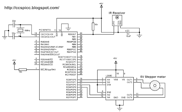
To control the bipolar stepper motor we need two H-bridge circuits and for that L293D motor driver chip is used, this cheap chip can work as a dual H-bridge drivers.
Project circuit schematic is shown below:
IR Remote controlled cd-rom bipolar stepper motor using PIC16F877A and L293D CCS PIC C
Remote controlled stepper motor using PIC16F877A CCS C code:
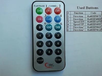
The IR remote control used in this project is shown below with the used buttons and their codes which are used in the code.
NEC IR remote control codes for stepper motor 
External interrupt is used for reading IR signals.
// Remote controlled bipolar stepper motor using PIC16F877A and L293D CCS C code
// http://ccspicc.blogspot.com/
// electronnote@gmail.com

#include <16F877A.h>
#fuses HS,NOWDT,NOPROTECT,NOLVP
#use delay(clock = 8000000)
#use fast_io(B)
#use fast_io(D)

unsigned int8 step_number = 0, speed_delay = 2;
unsigned int32 remote_code;
#INT_TIMER1                                  // Timer1 interrupt ISR
void timer1_isr(void){
  remote_code = 0;
  clear_interrupt(INT_TIMER1);
  disable_interrupts(INT_TIMER1);
}
#INT_EXT                                     // External interrupt ISR
void ext_isr(void){
  unsigned int8 count = 0, i;
  unsigned int32 ir_code;
  // Check 9ms pulse (remote control sends logic high)
  while((input(PIN_B0) == 0) && (count < 200)){
    count++;
    delay_us(50);}
  if( (count > 199) || (count < 160))        // NEC protocol?
    return;                          
  count = 0;
  // Check 4.5ms space or repeated code
  while((input(PIN_B0)) && (count < 100)){
    count++;
    delay_us(50);}
  if( (count > 99) || (count < 30))          // NEC protocol?
    return;
  // Check repeated code
  if(count < 60){
    count = 0;
    while((input(PIN_B0) == 0) && (count < 14)){
      count++;
      delay_us(50);}
    if( (count > 13) || (count < 8))         // NEC protocol?
      return;
    if((remote_code == 0x40BF50AF) || (remote_code == 0x40BF906F))
    set_timer1(0);
  }
  // Read message (32 bits)
  for(i = 0; i < 32; i++){
    count = 0;
    while((input(PIN_B0) == 0) && (count < 14)){
      count++;
      delay_us(50);}
    if( (count > 13) || (count < 8))         // NEC protocol?
      return;                          
    count = 0;
    while((input(PIN_B0)) && (count < 40)){
      count++;
      delay_us(50);}
    if( (count > 39) || (count < 8))         // NEC protocol?
      return;                           
    if( count > 20)                          // If space width > 1ms
      bit_set(ir_code, (31 - i));            // Write 1 to bit (31 - i)
    else                                     // If space width < 1ms
      bit_clear(ir_code, (31 - i));          // Write 0 to bit (31 - i)
  }
  if((ir_code == 0x40BF50AF) || (ir_code == 0x40BF906F)){
    set_timer1(0);
    clear_interrupt(INT_TIMER1);
    enable_interrupts(INT_TIMER1);}
  if(ir_code == 0x40BFA05F){
    speed_delay++;
    if(speed_delay > 20) speed_delay = 20;
    return;}
  if(ir_code == 0x40BF609F){
    speed_delay--;
    if(speed_delay < 2) speed_delay = 2;
    return;}
  remote_code = ir_code; 
}
void stepper(int8 step){
  switch(step){
    case 0:
      output_d(0b000000110);
    break;
    case 1:
      output_d(0b00000101);
    break;
    case 2:
      output_d(0b00001001);
    break;
    case 3:
      output_d(0b00001010);
    break;
  }
}
void main(){
  output_b(0);                                // PORTB initial state
  set_tris_b(0xF7);
  port_b_pullups(TRUE);                       // Enable PORTB internal pull-ups
  output_d(0);
  set_tris_d(0);
  setup_timer_1(T1_INTERNAL | T1_DIV_BY_4);   // Timer1 configuration
  enable_interrupts(GLOBAL);                  // Enable global interrupts
  enable_interrupts(INT_EXT_H2L);                 // Enable external interrupt
  while(TRUE){
    while(remote_code == 0);
    while((remote_code == 0x40BF40BF) || (remote_code == 0x40BF50AF)){
      step_number++;
      if(step_number > 3) 
        step_number = 0;
      stepper(step_number);
      delay_ms(speed_delay);
    }
    while((remote_code == 0x40BF807F) || (remote_code == 0x40BF906F)){
      if(step_number < 1) 
        step_number = 4;
      step_number--;
      stepper(step_number);
      delay_ms(speed_delay);
    }
  output_d(0);
  if((remote_code != 0x40BF40BF) && (remote_code != 0x40B807F))
  remote_code = 0;
  }
}

Remote controlled stepper motor using PIC16F877A video:
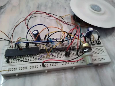
The following video shows a hardware circuit for this project.

Thursday, July 21, 2016

Unipolar Stepper Motor Control From IR Remote Control Using PIC18F4550


Remote controlled stepper motor using PIC18F4550
Car MP3 remote control controls 5V stepper motor using PIC microcontroller 
This project shows how to control a 5V unipolar stepper motor from IR remote control uses NEC protocol with PIC18F4550 microcontroller. This controller controls the stepper motor speed and direction of rotation.
If you want to see how to drive the unipolar stepper motor using PIC18F4550 microcontroller read the following topic:
Interfacing unipolar stepper motor with PIC18F4550 microcontroller
And if you want to see how to decode IR remote control with NEC protocol see the following topic:
Extended NEC IR remote control decoder with PIC18F4550 microcontroller
To drive the unipolar stepper motor we need ULN2003 (ULN2004) Darlington transistor array or L293D motor driver as described in the previous topic.
The IR remote control used in this project is shown below:
Car MP3 NEC protocol IR remote control
Project circuit schematic is shown below.
Remote controlled unipolar stepper motor using PIC18F4550 and NEC Car MP3 IR remote control circuit 
PIC18F4550 microcontroller internal oscillator is used.
Remote controlled unipolar stepper motor using PIC18F4550 CCS C code:
External interrupt is used to read IR remote control signals.
// Remote controlled stepper motor using PIC18F4550 CCS C code
// http://ccspicc.blogspot.com/
// electronnote@gmail.com

#include <18F4550.h>
#fuses NOMCLR INTRC_IO
#use delay(clock = 8000000)
#use fast_io(B)
#use fast_io(D)

short Direction;
unsigned int8 step_number = 0, speed_delay = 2;
unsigned int32 remote_code;
#INT_TIMER1                                  // Timer1 interrupt ISR
void timer1_isr(void){
  remote_code = 0;
  clear_interrupt(INT_TIMER1);
  disable_interrupts(INT_TIMER1);
}
#INT_EXT                                     // External interrupt ISR
void ext_isr(void){
  unsigned int8 count = 0, i;
  unsigned int32 ir_code;
  // Check 9ms pulse (remote control sends logic high)
  while((input(PIN_B0) == 0) && (count < 200)){
    count++;
    delay_us(50);}
  if( (count > 199) || (count < 160))        // NEC protocol?
    return;                          
  count = 0;
  // Check 4.5ms space or repeated code
  while((input(PIN_B0)) && (count < 100)){
    count++;
    delay_us(50);}
  if( (count > 99) || (count < 30))          // NEC protocol?
    return;
  // Check repeated code
  if(count < 60){
    count = 0;
    while((input(PIN_B0) == 0) && (count < 14)){
      count++;
      delay_us(50);}
    if( (count > 13) || (count < 8))         // NEC protocol?
      return;
    if((remote_code == 0x40BF50AF) || (remote_code == 0x40BF906F))
    set_timer1(0);
  }
  // Read message (32 bits)
  for(i = 0; i < 32; i++){
    count = 0;
    while((input(PIN_B0) == 0) && (count < 14)){
      count++;
      delay_us(50);}
    if( (count > 13) || (count < 8))         // NEC protocol?
      return;                          
    count = 0;
    while((input(PIN_B0)) && (count < 40)){
      count++;
      delay_us(50);}
    if( (count > 39) || (count < 8))         // NEC protocol?
      return;                           
    if( count > 20)                          // If space width > 1ms
      bit_set(ir_code, (31 - i));            // Write 1 to bit (31 - i)
    else                                     // If space width < 1ms
      bit_clear(ir_code, (31 - i));          // Write 0 to bit (31 - i)
  }
  if((ir_code == 0x40BF50AF) || (ir_code == 0x40BF906F)){
    set_timer1(0);
    clear_interrupt(INT_TIMER1);
    enable_interrupts(INT_TIMER1);}
  if(ir_code == 0x40BFA05F){
    speed_delay++;
    if(speed_delay > 20) speed_delay = 20;
    return;}
  if(ir_code == 0x40BF609F){
    speed_delay--;
    if(speed_delay < 2) speed_delay = 2;
    return;}
  remote_code = ir_code; 
}
void stepper(int8 step){
  if(Direction == 0){
    switch(step){
      case 0:
        output_d(0b00000011);
        break;
      case 1:
        output_d(0b00000110);
        break;
      case 2:
        output_d(0b00001100);
        break;
      case 3:
        output_d(0b00001001);
        break;
    }
  }
  if(Direction == 1){
    switch(step){
      case 0:
        output_d(0b00001001);
        break;
      case 1:
        output_d(0b00001100);
        break;
      case 2:
        output_d(0b00000110);
        break;
      case 3:
        output_d(0b00000011);
        break;
    }
  }
}
void main(){
  setup_oscillator(OSC_8MHZ);                 // Set internal oscillator to 8MHz
  setup_adc_ports(NO_ANALOGS);                // Configure AN pins as digital
  set_tris_b(1);                           // Configure RB0 as digital input pin
  port_b_pullups(TRUE);                       // Enable PORTB internal pull-ups
  output_d(0);                                // PORTD initial state
  set_tris_d(0);                              // Configure PORTD pins as outputs
  setup_timer_1(T1_INTERNAL | T1_DIV_BY_4);   // Timer1 configuration
  enable_interrupts(GLOBAL);                  // Enable global interrupts
  enable_interrupts(INT_EXT_H2L);                 // Enable external interrupt
  while(TRUE){
    output_d(0);
    while(remote_code == 0x40BF40BF){
      Direction = 0;
      stepper(step_number);
      step_number++;
      if(step_number > 3) 
        step_number = 0;
      delay_ms(speed_delay);
    }
    while(remote_code == 0x40BF807F){
      Direction = 1;
      stepper(step_number);
      step_number++;
      if(step_number > 3) 
        step_number = 0;
      delay_ms(speed_delay);
    }
    while(remote_code == 0x40BF50AF){
      Direction = 0;
      stepper(step_number);
      step_number++;
      if(step_number > 3) 
        step_number = 0;
      delay_ms(speed_delay);
    }
    while(remote_code == 0x40BF906F){
      Direction = 1;
      stepper(step_number);
      step_number++;
      if(step_number > 3) 
        step_number = 0;
      delay_ms(speed_delay);
    }
  }
}

Remote controlled unipolar stepper motor using PIC18F4550 video:

Tuesday, July 19, 2016

CD-ROM BLDC motor controller using PIC18F4550 and L293D


BLDC Motor controller using PIC18F4550 and L293D
BLDC motor ESC using PIC18F4550 and L293D 
In the following topic URL we've seen how to control BLDC motor speed and direction of rotation using PIC18F4550 microcontroller and 3-phase bridge circuit:
CD-ROM Spindle motor (BLDC) control with PIC18F4550 microcontroller
This topic shows how to make the same controller using L293D motor driver instead of the 3-phase bridge circuit.
The 3 phase bridge is more complicated and expansive and while the L293D motor driver chip is a small, cheap and saves time.
In this project we need two L293D chips because the BLDC motor is a three phase motor, and at any time two windings energized while the third one floating.
The L293D has 4 inputs and 4 outputs with 2 enable pins, each enable pin controls 2 outputs as shown below:
L293D Motor driver chip pinout BLDC motor
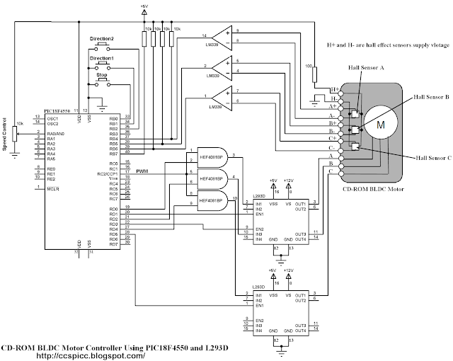
Complete circuit schematic is shown below:
Interfacing sensored BLDC motor with PIC18F4550 microcontroller and L293D circuit CCS PIC C
In the circuit there are 3 buttons connected to RB0, RB1 and RB2. The buttons connected to RB1 and RB2 are used to start the BLDC motor and the other button is a stop button.
The BLDC motor speed is controlled using a potentiometer connected to AN0 channel.
There are 3 AND gates (HEF4081BP) in the circuit, these gates are used to get a 3 PWM signals from the original one which comes from RC2 pin using CCP1 module.
HEF4081BP has 4 independent 2-input AND gates, three of them are used. This IC needs a supply voltage of +5V between pins 7 (GND) and 14 (VCC).
PIC18F4550 microcontroller internal oscillator is used (8MHz).
BLDC Motor control using PIC18F4550 and L293D CCS PIC C code:

// Sensored BLDC motor controller using PIC18F4550 and L293D CCS C code
// http://ccspicc.blogspot.com/
// electronnote@gmail.com

#include <18F4550.h>
#device ADC = 10
#fuses NOMCLR INTRC_IO
#use delay(clock = 8000000)
#use fast_io(B)
#use fast_io(D)

int8 hall, Direction = 0;
int8 MoveTable1[8] = {0, 50, 11, 56, 44, 14, 35, 0};
int8 MoveTable2[8] = {0, 35, 14, 44, 56, 11, 50, 0};
#INT_RB                                       // RB port interrupt on change
void rb_isr(void){
  hall = (input_b() >> 4) & 7;
  if(Direction == 1)
    output_d(MoveTable1[hall]);
  else
    output_d(MoveTable2[hall]);
  clear_interrupt(INT_RB);
}
void main(){
  setup_oscillator(OSC_8MHZ);                 // Set internal oscillator to 8MHz
  setup_adc_ports(AN0);                       // Configure RA0 (AN0) pin as analog
  output_b(0);                                // PORTB initial state
  set_tris_b(0xF7);                           // TRISB configurartion
  port_b_pullups(TRUE);                       // Enable PORTB internal pull-ups
  output_d(0);                                // PORTD initial state
  set_tris_d(0);                              // Configure PORTD pins as outputs
  setup_adc(ADC_CLOCK_DIV_8);                 // Set ADC conversion time to 64Tosc
  set_adc_channel(0);                         // Select channel 0 input
  setup_timer_2(T2_DIV_BY_1, 199, 1);         // Timer2 configuration for PWM
  setup_ccp1(CCP_OFF);
  enable_interrupts(GLOBAL);                  // Enable global interrupts
  while(TRUE){
    if(!input(PIN_B1)){                       // If RB1 button pressed
      if(Direction == 0){
        Direction = 1;
        setup_ccp1(CCP_PWM);                  // Configure CCP1 as a PWM
        clear_interrupt(INT_RB);              // Clear RB IOC flag bit
        enable_interrupts(INT_RB);            // Enable PORTB IOC
        hall = (input_b() >> 4) & 7;
        output_d(MoveTable1[hall]);
      }
    }
    if(!input(PIN_B2)){                       // If RB1 button pressed
      if(Direction == 0){
        Direction = 2;
        setup_ccp1(CCP_PWM);                  // Configure CCP1 as a PWM
        clear_interrupt(INT_RB);              // Clear RB IOC flag bit
        enable_interrupts(INT_RB);            // Enable PORTB IOC
        hall = (input_b() >> 4) & 7;
        output_d(MoveTable2[hall]);
      }
    }
    while(Direction != 0){
     set_pwm1_duty(read_adc());
     if(!input(PIN_B0)){
       disable_interrupts(INT_RB);             // Disable PORTB IOC
       output_d(0);
       setup_ccp1(CCP_OFF);                    // CCP1 OFF
       Direction = 0;
     }
   }
  }
}

BLDC Motor controller using PIC18F4550 and L293D video:
The following video shows project hardware circuit.


References:
Microchip: Sensored BLDC Motor Control Using dsPIC30F2010 (AN957).
Microchip: Brushless DC Motor Control Made Easy (AN857).
L293D Datasheet.

BLDC Motor control using PIC16F877A and L293D


Brushless DC motor control with PIC16F877A microcontroller and L293D driver
In this project:
Sensored brushless DC (BLDC) motor control with PIC16F877A microcontroller
I made a sensored BLDC motor speed controller using PIC16F877A and 3 phase bridge circuit.
In this project we are going to see how to build a BLDC motor controller using the same microcontroller and L293D motor driver chip instead of the 3 phase bridge circuit.
The 3 phase bridge is more complicated and expansive and while the L293D motor driver chip is a small, cheap and saves time.
In this project we need two L293D chips because the BLDC motor is a three phase motor, and at any time two windings energized while the third one floating.
The L293D has 4 inputs and 4 outputs with 2 enable pins, each enable pin controls 2 outputs as shown below:
L293D Half H-Bridge motor driver pinout
Complete circuit schematic is shown below:
Interfacing CD-ROM BLDC motor with PIC16F877A and L293D circuit CCS PIC C
In the circuit there are 3 buttons connected to RB0, RB1 and RB2. The buttons connected to RB1 and RB2 are used to start the BLDC motor and the other button is a stop button.
The BLDC motor speed is controlled using a potentiometer connected to AN0 channel.
There are 3 AND gates (HEF4081BP) in the circuit, these gates are used to get a 3 PWM signals from the original one which comes from RC2 pin using CCP1 module.
HEF4081BP has 4 independent 2-input AND gates, three of them are used. This IC needs a supply voltage of +5V between pins 7 (GND) and 14 (VCC).
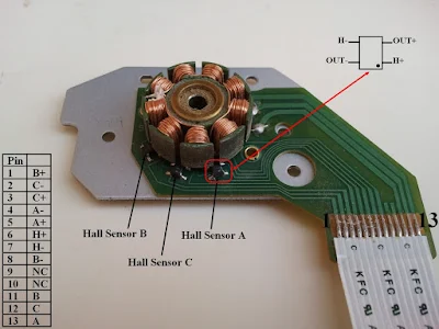
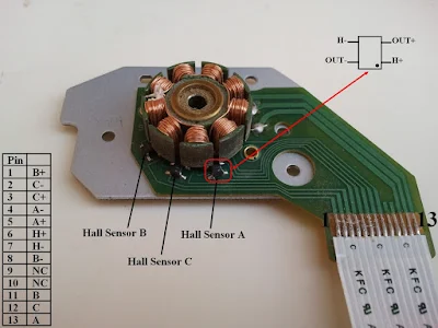
The CD-ROM BLDC motor pin configurations is shown in the following image:
CD-ROM DVD-ROM Brushless DC motor pin configuration PIC16F877A L293D
Each sensor outputs a digital high for 180 electrical degrees and outputs a digital low for the other 180 electrical degrees. The following figure shows the relationship between the sensors outputs and the required motor drive voltages for phases A, B and C.
Brushless DC motor timing PIC16F877A L293D
The 3 hall effect sensors needs 3 pins and for that RB4, RB5 and RB6 are used.
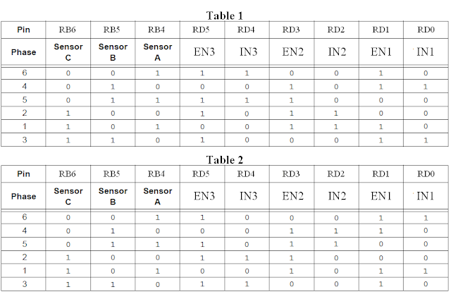
Two lookup tables are used for motor driver commutation according to the following two tables where table1 for direction 1 and table 2 for direction 2:
BLDC motor direction control table PIC16F877A L293D 
IN1, EN1, IN2 and EN2 are the 1st L293D pins which are respectively IN1, EN1, IN3, EN2.
IN3 and EN3 are the 2nd L293D IN1 and EN1.
BLDC Motor control using PIC16F877A and L293D CCS PIC C code:
// Sensored brushless DC motor control with PIC16F877A and L293D CCS C code
// http://ccspicc.blogspot.com/
// electronnote@gmail.com

#include <16F877A.h>
#fuses HS,NOWDT,NOPROTECT,NOLVP
#device ADC = 10
#use delay(clock = 8000000)
#use fast_io(B)
#use fast_io(D)

int8 hall, Direction = 0;
int8 MoveTable1[8] = {0, 50, 11, 56, 44, 14, 35, 0};
int8 MoveTable2[8] = {0, 35, 14, 44, 56, 11, 50, 0};
#INT_RB                                       // RB port interrupt on change
void rb_isr(void){
  hall = (input_b() >> 4) & 7;
  if(Direction == 1)
    output_d(MoveTable1[hall]);
  else
    output_d(MoveTable2[hall]);
  clear_interrupt(INT_RB);
}
void main(){
  output_b(0);                                // PORTB initial state
  set_tris_b(0xF7);
  port_b_pullups(TRUE);                       // Enable PORTB internal pull-ups
  output_d(0);
  set_tris_d(0);
  setup_adc(ADC_CLOCK_DIV_16);                // Set ADC conversion time to 16Tosc
  setup_adc_ports(AN0);                       // Configure AN0 as analog  
  set_adc_channel(0);                         // Select channel 0 input
  setup_timer_2(T2_DIV_BY_1, 199, 1);         // Set PWM frequency to 10KHz
  setup_ccp1(CCP_OFF);                        // CCP1 OFF
  enable_interrupts(GLOBAL);
  while(TRUE){
    if(!input(PIN_B1)){                       // If RB1 button pressed
      if(Direction == 0){
        Direction = 1;
        setup_ccp1(CCP_PWM);                  // Configure CCP1 as a PWM
        clear_interrupt(INT_RB);              // Clear RB IOC flag bit
        enable_interrupts(INT_RB);            // Enable PORTB IOC
        hall = (input_b() >> 4) & 7;
        output_d(MoveTable1[hall]);
      }
    }
    if(!input(PIN_B2)){                       // If RB1 button pressed
      if(Direction == 0){
        Direction = 2;
        setup_ccp1(CCP_PWM);                  // Configure CCP1 as a PWM
        clear_interrupt(INT_RB);              // Clear RB IOC flag bit
        enable_interrupts(INT_RB);            // Enable PORTB IOC
        hall = (input_b() >> 4) & 7;
        output_d(MoveTable2[hall]);
      }
    }
    while(Direction != 0){
     set_pwm1_duty(read_adc());
     if(!input(PIN_B0)){
       disable_interrupts(INT_RB);             // Disable PORTB IOC
       output_d(0);
       setup_ccp1(CCP_OFF);                    // CCP1 OFF
       Direction = 0;
     }
   }
  }
}

CD-ROM BLDC Motor control using PIC16F877A and L293D:
The following video shows project hardware circuit.

References:
Microchip: Sensored BLDC Motor Control Using dsPIC30F2010 (AN957).
Microchip: Brushless DC Motor Control Made Easy (AN857).
L293D Datasheet.

Sunday, July 17, 2016

CD-ROM Spindle motor (BLDC) control with PIC18F4550 microcontroller


CD-ROM Sensored brushless (BLDC) motor control using PIC18F4550 microcontroller
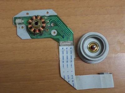
CD DVD-ROM Spindle BLDC motor rotor removed 
This topic shows an easy way for controlling cd-rom drive (or dvd-rom) spindle motor using PIC18F4550 microcontroller.
There are different spindle motor types used in the cd-rom drives and the one used here is sensored brushless DC motor (BLDC motor), so be careful with your BLDC motor type and if it has less than 11 pins that means your motor is not concerned.
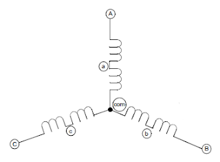
This motor is three phase motor, it has three stator phases that are excited two at a time to create arotating electric field. This method is fairly easy to implement, but to prevent the permanent magnet rotor from getting locked with the stator, the excitation on the stator must be sequenced in a specific manner while knowing the exact position of the rotor magnets.
3 Phase BLDC motor winding PIC18F4550
The sensored BLDC motor has 3 hall effect sensors (Sensor A, Sensor B and Sensor C) to sense rotor position, this sensors are placed as shown in the following picture with pinout configuration:
CD-ROM DVD-ROM Brushless DC motor (BLDC) pinout PIC18F4550
Each sensor outputs a digital high for 180 electrical degrees and outputs a digital low for the other 180 electrical degrees. The following figure shows the relationship between the sensors outputs and the required motor drive voltages for phases A, B and C.
Brushless DC motor (BLDC) hall effect sensors timing PIC18F4550
A three phase bridge is used to energize the BLDC motor windings.
Brushless DC motor (BLDC) 3 phase bridge PIC18F4550
Each phase driver requires 2 pins one for the high side and the other one for the low side which means a total of 6 pins are required to drive the three phase bridge. In this project 6 pins of PORTD will be used.
The 3 hall effect sensors needs 3 pins and for that RB4, RB5 and RB6 are used.
Two lookup tables are used for motor driver commutation according to the following two tables where table1 for direction 1 and table 2 for direction 2:
Table 1
Brushless DC motor (BLDC) direction 1 table PIC18F4550 
Rotation direction2 is accomplished by driving current through the motor coils in the direction opposite of that for rotation direction1.
 Table 2
Brushless DC motor (BLDC) direction 2 table PIC18F4550
CD-ROM sensored brushless DC (BLDC) motor speed and direction control using PIC18F4550 microcontroller:
The following image shows project circuit schematic diagram.
CD-ROM Sensored spindle Brushless DC motor (BLDC) control circuit using PIC18F4550 CCS PIC C 
In the circuit there are 3 pushbuttons connected to RB0, RB1 and RB2. The buttons connected to RB1 and RB2 are for starting the BLDC motor direction1 or direction2, and RB0 button stops the BLDC motor.
Each hall effect sensor has 4 pins:
H+ and H- : sensor power supply pins
OUT+ and OUT- : sensor output pins.
For the system power supply there is +5V and +12V. The +12V supplies the 3 phase bridge circuit which is the same as the motor supply voltage.
LM339 consists of four independent precision voltage comparators. 3 camparators are needed for the 3 hall effect sensors as shown in the circuit schematic above. LM339 needs +5V power supply voltage  which is connected as shown below:
BLDC motor with LM339 comparator PIC18F4550
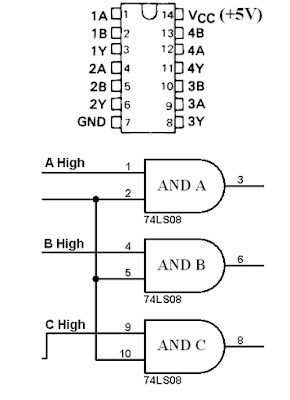
74LS08 contains four independent 2-input AND gates. 3 AND gates are needed to make 3 PWM signals. The 74LS08 must be supplied with +5V as shown below:
BLDC motor with 74LS08 AND gates for PWM PIC18F4550
CD-ROM sensored brushless DC (BLDC) motor control with PIC18F4550 microcontroller CCS PIC C compiler code:
This is the full code of this project. The code is small and not complicated.
RB interrupt on change (IOC) is used to interrupt when the rotor changes its position.
A potentiometer connected to analog channel 0 is used to control the BLDC motor speed in both directions.
// CD-ROM Sensored BLDC motor control with PIC18F4550 CCS C code
// http://ccspicc.blogspot.com/
// electronnote@gmail.com

#include <18F4550.h>
#device ADC = 10
#fuses NOMCLR HSPLL PLL2 CPUDIV1
#use delay(clock = 48000000)
#use fast_io(B)
#use fast_io(D)

int8 hall, Direction = 0;
const int8 MoveTable1[8] = {0, 33, 6, 36, 24, 9, 18, 0};
const int8 MoveTable2[8] = {0, 18, 9, 24, 36, 6, 33, 0};
#INT_EXT                                      // External interrupt ISR
void ext_isr(void){
  disable_interrupts(INT_RB);
  output_d(0);
  setup_ccp1(CCP_OFF);                        // CCP1 OFF
  Direction = 0;
  clear_interrupt(INT_EXT);
}
#INT_RB                                       // RB port interrupt on change ISR
void rb_isr(void){
  hall = (input_b() >> 4) & 7;
  if(Direction == 1)
    output_d(MoveTable1[hall]);
  else
    output_d(MoveTable2[hall]);
  clear_interrupt(INT_RB);
}
void main(){
  setup_adc_ports(AN0);                       // Configure RA0 (AN0) pin as analog
  output_b(0);                                // PORTB initial state
  set_tris_b(0xF7);                           // TRISB configurartion
  port_b_pullups(TRUE);                       // Enable PORTB internal pull-ups
  output_d(0);                                // PORTD initial state
  set_tris_d(0);                              // Configure PORTD pins as outputs
  setup_adc(ADC_CLOCK_DIV_64);                // Set ADC conversion time to 64Tosc
  set_adc_channel(0);                         // Select channel 0 input
  setup_timer_2(T2_DIV_BY_16, 250, 1);        // Timer2 configuration for PWM
  setup_ccp1(CCP_OFF);
  enable_interrupts(GLOBAL);                  // Enable global interrupts
  enable_interrupts(INT_EXT);                 // Enable external interrupt
  delay_ms(100);                              // Wait 100ms
  while(TRUE){
    if(!input(PIN_B1)){                       // If RB1 button pressed
      if(Direction == 0){
        Direction = 1;
        setup_ccp1(CCP_PWM);                  // Configure CCP1 as a PWM
        clear_interrupt(INT_RB);              // Clear RB IOC flag bit
        enable_interrupts(INT_RB);            // Enable PORTB IOC
        hall = (input_b() >> 4) & 7;
        output_d(MoveTable1[hall]);
      }
    }
    if(!input(PIN_B2)){                       // If RB1 button pressed
      if(Direction == 0){
        Direction = 2;
        setup_ccp1(CCP_PWM);                  // Configure CCP1 as a PWM
        clear_interrupt(INT_RB);              // Clear RB IOC flag bit
        enable_interrupts(INT_RB);            // Enable PORTB IOC
        hall = (input_b() >> 4) & 7;
        output_d(MoveTable2[hall]);
      }
    }
   while(Direction != 0){
     set_pwm1_duty(read_adc());
   }
  }
}

CD-ROM BLDC motor control with PIC18F4550 microcontroller:
The following video shows a hardware circuit for this project.

References:
Microchip: Sensored BLDC Motor Control Using dsPIC30F2010 (AN957).
Microchip: Brushless DC Motor Control Made Easy (AN857).

Friday, July 15, 2016

Sensored brushless DC (BLDC) motor control with PIC16F877A microcontroller


Sensored BLDC motor control using PIC16F877A - CCS PIC C compiler
This topic shows an easy way to drive a Cd-Rom sensored brushless DC motor (BLDC motor) using PIC16F877A microcontroller with CCS PIC C code.
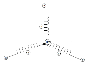
3 phase Brushless BLDC motor 
This motor is three phase motor, it has three stator phases that are excited two at a time to create arotating electric field. This method is fairly easy to implement, but to prevent the permanent magnet rotor from getting locked with the stator, the excitation on the stator must be sequenced in a specific manner while knowing the exact position of the rotor magnets.
The sensored BLDC motor has 3 hall effect sensors (Sensor A, Sensor B and Sensor C), this sensors sense the rotor position. Each sensor outputs a digital high for 180 electrical degrees and outputs a digital low for the other 180 electrical degrees. The following figure shows the relationship between the sensors outputs and the required motor drive voltages for phases A, B and C.
3 phase Brushless BLDC motor and hall effect sensors timing
A three phase bridge is used to energize the BLDC motor windings.
3 phase bridge for Brushless BLDC motor
Each phase driver requires 2 pins one for the high side and the other one for the low side which means a total of 6 pins are required to drive the three phase bridge. In this project 6 pins of PORTD will be used.
The 3 hall effect sensors needs 3 pins and for that RB4, RB5 and RB6 are used.
A lookup table is used to commutate the motor driver according to the following table:
BLDC motor and hall effect sensors commutaion table
CD-ROM sensored brushless DC (BLDC) motor speed control with PIC16F877A microcontroller:
The following image shows project circuit schematic diagram.
CD-ROM sensored BLDC motor control using PIC16F877A microcontroller circuit CCS PIC C 
LM339 consists of four independent precision voltage comparators. 3 camparators are needed for the 3 hall effect sensors as shown in the circuit schematic above. A +5V is needed for the LM339 chip as shown below:
LM339 comparator for BLDC motor
74LS08 contains four independent 2-input AND gates. 3 AND gates are needed to make 3 PWM signals. The 74LS08 must be supplied with +5V as shown below:
SN74LS08 AND gates for BLDC motor PWM
The CD-ROM BLDC motor pin configurations is shown in the following image where the rotor has been removed :
CD-ROM sensored brushless DC motor pin configuration
In this BLDC motor each hall effect sensor has 4 pins:
H+ and H- : sensor power supply pins
OUT+ and OUT- : sensor output pins.
For the system power supply there is +5V and +12V. The +12V supplies the 3 phase bridge circuit which is the same as the motor supply voltage.
CD-ROM sensored brushless DC (BLDC) motor control with PIC16F877A microcontroller CCS PIC C compiler code:
This is the full code of this project. The code is small and not complicated.
RB interrupt on change (IOC) is used to interrupt when the rotor changes its position.
A potentiometer connected to analog channel 0 is used to control the BLDC motor speed.
The PWM frequency is 500Hz and the duty cycle is related to analog channel 0 reading.

// CD-ROM Sensored BLDC motor control with PIC16F877A CCS C code
// http://ccspicc.blogspot.com/
// electronnote@gmail.com

#include <16F877A.h>
#fuses HS,NOWDT,NOPROTECT,NOLVP
#device ADC = 10
#use delay(clock = 8000000)
#use fast_io(B)
#use fast_io(D)

int8 hall;
int8 MoveTable[8] = {0, 33, 6, 36, 24, 9, 18, 0};
int16 value;
#INT_RB                                       // RB port interrupt on change
void rb_isr(void){
  hall = (input_b() >> 4) & 7;          
  output_d(MoveTable[hall]);
  clear_interrupt(INT_RB);
}
void main(){
  output_b(0);                                // PORTB initial state
  set_tris_b(0xF3);
  port_b_pullups(TRUE);                       // Enable PORTB internal pull-ups
  output_d(0);
  set_tris_d(0);
  setup_adc(ADC_CLOCK_DIV_16);                // Set ADC conversion time to 16Tosc
  setup_adc_ports(AN0);                       // Configure AN0 as analog  
  set_adc_channel(0);                         // Select channel 0 input
  setup_timer_2(T2_DIV_BY_16, 250, 1);        // Set PWM frequency to 500Hz
  setup_ccp1(CCP_OFF);                        // CCP1 OFF
  enable_interrupts(GLOBAL);                
  delay_ms(100);                              // Wait 100ms
  while(TRUE){
    if(!input(PIN_B0)){                       // If RB0 button pressed
      if(input(PIN_B2)){                      // Check if motor is already running
        disable_interrupts(INT_RB);
        output_d(0);
        setup_ccp1(CCP_OFF);                  // CCP1 OFF
        output_low(PIN_B2);                   // RB2 LED OFF
      }
    }
    if(!input(PIN_B1)){                       // If RB1 button pressed
      if(!input(PIN_B2)){                     // Check if motor is already running
        output_high(PIN_B2);                  // RB2 LED ON
        clear_interrupt(INT_RB);              // Clear RB IOC flag bit
        enable_interrupts(INT_RB);            // Enable PORTB IOC
        setup_ccp1(CCP_PWM);                  // Configure CCP1 as a PWM
        hall = (input_b() >> 4) & 7;
        output_d(MoveTable[hall]);
      }
    }
    if(input(PIN_B2)){
      read_adc(ADC_START_ONLY);
      while(!adc_done());                     // Wait until conversion complete
      value = read_adc(ADC_READ_ONLY);        // Read ADC value
      set_pwm1_duty(value);                   // Set PWM duty cycle
    }
  }
}

CD-ROM BLDC motor control with PIC16F877A microcontroller:
The following video shows a hardware circuit for this project..

References:
Microchip: Sensored BLDC Motor Control Using dsPIC30F2010 (AN957).
Microchip: Brushless DC Motor Control Made Easy (AN857).

Sunday, July 10, 2016

Extended NEC IR remote control decoder with PIC18F4550 microcontroller


Extended NEC protocol decoder
 
The NEC protocol uses pulse distance encoding of the bits. Each pulse is a 562.5µs long with carrier frequency of 38KHz. Logic bits are transmitted as follows:
Logic 0: 562.5µs pulse burst followed by a 562.5µs space, with a total transmit time of 1125µs (562.5 x 2).
Logic 1: a 562.5µs pulse burst followed by a 1687.5µs (562.5 x 3) space, with a total transmit time of 2250µs (562.5 x 4).
Extended NEC protocol data send
The complete extended NEC protocol message is started by 9ms burst followed by 4.5ms space which is then followed by the Address and Command. The address is 16-bit length and the command is transmitted twice (8 bits + 8 bits) where in the second time all bits are inverted and can be used for verification of the received message. The following drawing shows an extended NEC message example.
Extended NEC protocol one code message 
NEC Protocol IR remote control decoder with PIC18F4550 microcontroller:
It is easy to decode IR remote control uses NEC protocol using microcontrollers.
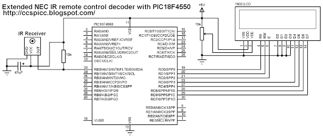
Here Microchip PIC18F4550 microcontroller is used to decode IR remote controls which uses NEC and extended NEC protocol. Decoder circuit schematic is shown below.
Extended NEC protocol for IR remote control decoder using PIC18F4550 circuit - CCS PIC C 
In this project PIC18F4550 internal oscillator is used @ 8MHz.
NEC Protocol IR remote control decoder with PIC18F4550 CCS C code:
There are different ways to decode the NEC protocol for example using CCP module and Timer module, using Timer module or using port change interrupt........ In this project I didn't use any interrupt or Timer, I used delay command to make the code as simple as possible with time-out property and the code checks the IR signal with resolution of 50µs.
Programming hints:
From the decoder circuit schematic above the output of the IR receiver is connected to RB0 and when an IR signal is received RB0 pin goes from logic high (+5V) to logic low (0V).
The NEC message has 32 bits which are divided into address (16 bits), command (8 bits) and inverted command (8 bits).
The microcontroller waits until the IR receiver receives an IR signal which makes RB0 goes from logic high to logic low and the command used is:
while(input(PIN_B0));
After that a function named nec_remote_read() is called, this function checks if the received signal has NEC protocol form all the time.
The last function reads the 9ms burst using the following lines and if the pulse is more than 10ms (50µs x 200) or less than 8ms (50µs x 160) the function returns with false result which means the received signal doesn't have NEC protocol form.
while((input(PIN_B0) == 0) && (count < 200)){
    count++;
    delay_us(50);}
if( (count > 199) || (count < 160))
    return false;
The 4.5ms space is checked as the 9ms burst with small differences:
while((input(PIN_B0)) && (count < 100)){
    count++;
    delay_us(50);}
  if( (count > 99) || (count < 60))
    return false;
After that the microcontroller starts reading the 32 bits and keeps checking of NEC protocol form.
The following code is the complete CCS PIC C code written with compiler PCWHD version 5.051.
// Extended NEC Protocol IR remote control decoder using PIC18F4550 CCS C code
// http://ccspicc.blogspot.com/
// electronnote@gmail.com

//LCD module connections
#define LCD_RS_PIN PIN_D0
#define LCD_RW_PIN PIN_D1
#define LCD_ENABLE_PIN PIN_D2
#define LCD_DATA4 PIN_D3
#define LCD_DATA5 PIN_D4
#define LCD_DATA6 PIN_D5
#define LCD_DATA7 PIN_D6
//End LCD module connections

#include <18F4550.h>
#fuses NOMCLR INTRC_IO
#use delay(clock = 8000000)
#include <lcd.c>
#use fast_io(B)

unsigned int32 ir_code;
unsigned int16 address;
unsigned int8 command, inv_command;
short nec_remote_read(){
  unsigned int8 count = 0, i;
  // Check 9ms pulse (remote control sends logic high)
  while((input(PIN_B0) == 0) && (count < 200)){
    count++;
    delay_us(50);}
  if( (count > 199) || (count < 160))        // NEC protocol?
    return FALSE;                          
  count = 0;
  // Check 4.5ms space (remote control sends logic low)
  while((input(PIN_B0)) && (count < 100)){
    count++;
    delay_us(50);}
  if( (count > 99) || (count < 60))          // NEC protocol?
    return FALSE;                         
  // Read message (32 bits)
  for(i = 0; i < 32; i++){
    count = 0;
    while((input(PIN_B0) == 0) && (count < 14)){
      count++;
      delay_us(50);}
    if( (count > 13) || (count < 8))         // NEC protocol?
      return FALSE;                          
    count = 0;
    while((input(PIN_B0)) && (count < 40)){
      count++;
      delay_us(50);}
    if( (count > 39) || (count < 8))         // NEC protocol?
      return FALSE;                           
    if( count > 20)                          // If space width > 1ms
      bit_set(ir_code, (31 - i));            // Write 1 to bit (31 - i)
    else                                     // If space width < 1ms
      bit_clear(ir_code, (31 - i));          // Write 0 to bit (31 - i)
  }
  return TRUE;
}
void main(){
  setup_oscillator(OSC_8MHZ);                // Set internal oscillator to 8MHz
  setup_adc_ports(NO_ANALOGS);               // Configure AN pins as digital
  set_tris_b(1);                             // Configure RB0 as digital input pin
  lcd_init();                                // Initialize LCD module
  lcd_putc('\f');                            // LCD clear
  lcd_gotoxy(3, 1);                          // Go to column 3 row 1
  lcd_putc("NEC Protocol");
  lcd_gotoxy(5, 2);                          // Go to column 5 row 2
  lcd_putc("Decoder");
  delay_ms(2000);
  lcd_putc('\f');
  lcd_gotoxy(1, 1);                          // Go to column 1 row 1
  printf(lcd_putc, "Address:0x0000");
  lcd_gotoxy(1, 2);                          // Go to column 1 row 2
  printf(lcd_putc, "Com:0x00 In:0x00");
  while(TRUE){
    while(input(PIN_B0));                    // Wait until RB0 pin falls
    if(nec_remote_read()){
      address = ir_code >> 16;
      command = ir_code >> 8;
      inv_command = ir_code;
      lcd_gotoxy(11, 1);               
      printf(lcd_putc,"%4LX",address);  
      lcd_gotoxy(7, 2);          
      printf(lcd_putc,"%2X",command); 
      lcd_gotoxy(15, 2);          
      printf(lcd_putc,"%2X",inv_command);
      delay_ms(200);}
  }
}

NEC Protocol IR remote control decoder with PIC18F4550 video:
The following video shows how this decoder works in a hardware circuit.
Reference:
http://www.sbprojects.com/