Monday, September 25, 2017

Remote controlled USB mouse using PIC18F4550


Building a USB mouse using PIC18F4550 microcontroller and CCS C compiler is easy as shown in the link below:
USB Mouse using PIC18F4550 microcontroller
Also, it is not hard to add an infrared remote control to the previous USB project. This post shows how did I build a simple IR remote controlled USB mouse using PIC18F4550 microcontroller and Car MP3 IR remote control (NEC protocol).
The link below shows how to decode NEC IR remote control (remote controls may not have the same code messages, so to know the code of each button we've to decode it first):
NEC Protocol decoder with PIC16F887 microcontroller
Hardware Required:
  • PIC18F4550 microcontroller
  • IR remote control (NEC protocol)
  • IR receiver
  • 8MHz Crystal Oscillator
  • 2 x 22pF capacitors
  • 47uF polarized capacitor
  • 470nF Capacitor
  • 10K ohm resistor
  • USB Connector
  • +5V Power Supply (USB VCC can be used)
  • Breadboard
  • Jumper Wires
Remote controlled USB mouse using PIC18F4550 circuit:
Remote controlled USB mouse using PIC18F4550 circuit 
The IR receiver has 3 pins: GND, VCC and OUT. The OUT pin is connected to RB0 (INT0 pin).
The circuit shown above is powered from an external 5V source which means there is no need to connect the VCC pin of the USB connector, but this pin can be used to supply the circuit and therefore the external 5V source has to be removed.
In this project the microcontroller runs with 8 MHz crystal oscillator and MCLR pin function is disabled.
Remote controlled USB mouse using PIC18F4550 C code:
The C code below was tested with CCS C compiler version 5.051.
In this project the PIC18F4550 MCU runs with 8 MHz crystal oscillator and it is configured so that the MCU runs at 8 MHz. I enabled PLL2 for the USB module in order to get 48 MHz which allows the USB module to run at full speed (12 Mbps).
The output of the IR receiver is connected to the external interrupt 0 pin (RB0/INT0) and with that I used it to decode the IR remote control. The NEC code massage is 32-bit long (2 words).
I used Timer1 to measure pulse and space widths and I used Timer1 interrupt to reset the decoding process in case of very long pulse or very long space (time out). Timer1 is configured to increment every 1 us. So for example for the 9 ms pulse I used the interval between 8500 and 9500.
I used Timer3 with the repeated remote control codes. If a button is pressed with hold the remote control will send the button massage code and then it sends 9 ms pulse --> 2.5 ms space --> 562 us pulse and so on every 110 ms. (more details at: http://www.sbprojects.com/knowledge/ir/nec.php)
From previous if a button is pressed with hold it will continuously sets Timer3 to the value 25000 ( set_timer3(25000); ). When the button is released Timer3 will overflow and its interrupt will reset the code message ( nec_code = 0; ).


The function usb_put_packet(1, out_data, 4, USB_DTS_TOGGLE); sends a packet of 4 bytes from the array out_data over USB.The variable array out_data is a 4-byte array where:
Byte 1 corresponds to button status. The left button of the mouse is represented by 1 and the right button is represented by 3.
Byte 2 and byte 3 correspond to X axis and Y axis directions respectively.
Byte 4 for the mouse wheel which is not used in this project.
The X axis and Y axis bytes are signed int8 which can vary from -127 to 127. The ( - ) sign indicates direction ( for X axis left/right and for Y axis up/down) and the number means number of steps at a time.
The remote control which I used is shown below:
Car MP3 IR remote control
I used the buttons numbered from 1 to 6 where:

Button Number Function Code
1 Left button 0x40BF30CF
2 Move cursor up 0x40BFB04F
3 Right button 0x40BF708F
4 Move cursor left 0x40BF08F7
5 Move cursor down 0x40BF8877
6 Move cursor right 0x40BF48B7

The complete C code is below.
// IR Remote controlled USB mouse using PIC18F4550 microcontroller CCS C code.
// Car MP3 IR remote control is used (NEC protocol)
// http://ccspicc.blogspot.com/
// electronnote@gmail.com

#include <18F4550.h>
#fuses  HS, CPUDIV1, PLL2, USBDIV, VREGEN, NOMCLR, NOWDT, NOLVP
#use delay(clock = 8MHz)
#include <usb_desc_mouse.h>
#include<pic18_usb.h>
#include<usb.c>

signed int8 out_data[4] = {0, 0, 0, 0};
short nec_ok = 0, repeated = 0;
int8 i, nec_state = 0;
int32 nec_code;
#INT_EXT                                         // External interrupt
void ext_isr(void){
  int16 time;
  if(nec_state != 0){
    time = get_timer1();                         // Store Timer1 value
    set_timer1(0);                               // Reset Timer1
  }
  switch(nec_state){
    case 0 :                                     // Start receiving IR data (we're at the beginning of 9ms pulse)
      setup_timer_1( T1_INTERNAL | T1_DIV_BY_2 );   // Enable Timer1 module with internal clock source and prescaler = 2
      set_timer1(0);                             // Reset Timer1 value
      nec_state = 1;                             // Next state: end of 9ms pulse (start of 4.5ms space)
      i = 0;
      ext_int_edge( L_TO_H );                    // Toggle external interrupt edge
      return;
    case 1 :                                     // End of 9ms pulse
      if((time > 9500) || (time < 8500)){        // Invalid interval ==> stop decoding and reset
        nec_state = 0;                           // Reset decoding process
        setup_timer_1(T1_DISABLED);              // Stop Timer1 module
      }
      else
        nec_state = 2;                           // Next state: end of 4.5ms space (start of 562µs pulse)
      ext_int_edge( H_TO_L );                    // Toggle external interrupt edge
      return;
    case 2 :                                     // End of 4.5ms space
      if((time > 5000) || (time < 1500)){        // Invalid interval ==> stop decoding and reset
        nec_state = 0;                           // Reset decoding process
        setup_timer_1(T1_DISABLED);              // Stop Timer1 module
        return;
      }
      nec_state = 3;                             // Next state: end of 562µs pulse (start of 562µs or 1687µs space)
      if(time < 3000)                            // Check if previous code is repeated
        repeated = 1;
      ext_int_edge( L_TO_H );                    // Toggle external interrupt edge
      return;
    case 3 :                                     // End of 562µs pulse
      if((time > 700) || (time < 400)){          // Invalid interval ==> stop decoding and reset
        nec_state = 0;                           // Reset decoding process
        setup_timer_1(T1_DISABLED);              // Disable Timer1 module
      }
      else{
        // Check if the code is repeated
        if(repeated){
          set_timer3(25000);
          repeated = 0;
          nec_ok = 1;                            // Decoding process is finished with success
          return;
        }
        nec_state = 4;                           // Next state: end of 562µs or 1687µs space
      }
      ext_int_edge( H_TO_L );                    // Toggle external interrupt edge
      return;
    case 4 :                                     // End of 562µs or 1687µs space
      if((time > 1800) || (time < 400)){         // Invalid interval ==> stop decoding and reset
        nec_state = 0;                           // Reset decoding process
        setup_timer_1(T1_DISABLED);              // Disable Timer1 module
        return;
      }
      if( time > 1000)                           // If space width > 1ms (short space)
        bit_set(nec_code, (31 - i));             // Write 1 to bit (31 - i)
      else                                       // If space width < 1ms (long space)
        bit_clear(nec_code, (31 - i));           // Write 0 to bit (31 - i)
      i++;
      if(i > 31){                                // If all bits are received
        nec_ok = 1;                              // Decoding process OK
      }
      nec_state = 3;                             // Next state: end of 562µs pulse (start of 562µs or 1687µs space)
      ext_int_edge( L_TO_H );                    // Toggle external interrupt edge
  }
}
#INT_TIMER1                                      // Timer1 interrupt (used for time out)
void timer1_isr(void){
  nec_ok = 0;
  nec_state = 0;                                 // Reset decoding process
  ext_int_edge( H_TO_L );                        // External interrupt edge from high to low
  setup_timer_1(T1_DISABLED);                    // Disable Timer1 module
  clear_interrupt(INT_TIMER1);                   // Clear Timer1 interrupt flag bit
}
#INT_TIMER3                                      // Timer1 interrupt (used for time out)
void timer3_isr(void){
  nec_code = 0;
  setup_timer_3(T3_DISABLED);                    // Disable Timer3 module
  clear_interrupt(INT_TIMER3);                   // Clear Timer3 interrupt flag bit
}
void main(){
  delay_ms(500);
  usb_init();                                    // Initialize USB hardware
  enable_interrupts(GLOBAL);                     // Enable global interrupts
  enable_interrupts(PERIPH);
  enable_interrupts(INT_EXT_H2L);                // Enable external interrupt
  clear_interrupt(INT_TIMER1);                   // Clear Timer1 interrupt flag bit
  enable_interrupts(INT_TIMER1);                 // Enable Timer1 interrupt
  clear_interrupt(INT_TIMER3);                   // Clear Timer3 interrupt flag bit
  enable_interrupts(INT_TIMER3);                 // Enable Timer3 interrupt
  while(TRUE){
    if(nec_ok){                                  // If the mcu successfully receives NEC protocol message
      nec_ok = 0;                                // Reset decoding process
      nec_state = 0;
      setup_timer_1(T1_DISABLED);                // Disable Timer1 module
      set_timer3(25000);
      setup_timer_3( T3_INTERNAL | T1_DIV_BY_8 );    // Enable Timer3 module with internal clock source and prescaler = 8 
      if(nec_code == 0x40BF30CF)                 // Button 1 code (mouse left button)
        out_data[0] = 1;
      if(nec_code == 0x40BFB04F)                 // Button 2 code (move cursor up)
        out_data[2] = -1;
      if(nec_code == 0x40BF708F)                 // Button 3 code (mouse right button)
        out_data[0] = 3;
      if(nec_code == 0x40BF08F7)                 // Button 4 code (move cursor left)
        out_data[1] = -1;
      if(nec_code == 0x40BF8877)                 // Button 5 code (move cursor down)
        out_data[2] = 1;
      if(nec_code == 0x40BF48B7)                 // Button 6 code (move cursor right)
        out_data[1] = 1;
      while(nec_code != 0)
        usb_put_packet(1, out_data, 4, USB_DTS_TOGGLE);    // Send USB packet
      delay_ms(10);
      out_data[0] = 0;
      out_data[1] = 0;
      out_data[2] = 0;
      usb_put_packet(1, out_data, 4, USB_DTS_TOGGLE);      // Send USB packet
    }
  }
}
Remote controlled USB mouse using PIC18F4550 video:
The following video is divided into 2 parts, part shows PC screen which is the main part and the small part shows my simple hardware circuit (sorry for video quality).


Interfacing PIC24FJ64GB002 with LCD


 PIC24FJ64GB002 16-bit MCU with 1602 LCD hardware circuit
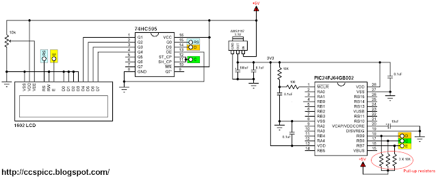
This post shows how to interface LCD screen (16x2, 20x'4 ....) with PIC24FJ64GB002 microcontroller where the compiler used is CCS C.
The PIC24FJ64GB002 is a 16-bit microcontroller runs with 3.3V while is the LCD used in this example is 5V. The PIC24FJ64GB002 has some 5.5V tolerant input pins (RB5, RB7, RB8, RB9, RB10 and RB11), with this pins we can apply 5V to the microcontroller without any problem.
An other good thing with this microcontroller is the open drain outputs, each output pin can be configured to work as an open drain output.
In this project I used a serial-in parallel-out shift register to minimize number of pins used by the LCD because we don't have enough 5.5V tolerant input pins to connect another 5V device. With the shift register the LCD will use only 3 pins which means we've gained at least 3 pins.
Hardware Required:
  • PIC24FJ64GB002 microcontroller
  • AMS1117 3V3 voltage regulator
  • 16x2 LCD screen
  • 74HC595 shift register (74HC164N and CD4094 also work)
  • 100uF polarized capacitor
  • 10uF polarized capacitor
  • 4 x 0.1uF ceramic capacitor
  • 4 x 10K ohm resistor
  • 10K variable resistor
  • 100 ohm resistor
  • 5V power source
  • Breadboard
  • Jumper wires
Interfacing PIC24FJ64GB002 with LCD circuit:
PIC24FJ64GB002 microcontroller with 16x2 LCD circuit diagram
In this example the PIC24FJ64GB002 MCU runs with its internal oscillator.
The AMS1117 3V3 voltage regulator is used to supply the MCU with 3.3V from the 5V source.
The E (Enable) pin of the LCD screen is connected directly to pin RB7 (#16) of the microcontroller. The C (Clock) pin of the shift register is connected to pin RB8 (#17) of the microcontroller. The last shift register pin which named D (Data) is connected to pin RB9 (#18) of the microcontroller.
The three pins: RB7, RB8 and RB9 are 5.5V tolerant input pins and can be configured to be an open drain outputs. With the open drain outputs and 5V pull up resistors we get what our LCD needs (logic 0 of 0V and logic 1 of 5V).
Interfacing PIC24FJ64GB002 with LCD C code:
The C code below was tested with CCS C compiler version 5.051.
To be able to compile the code below a 3-wire LCD driver has to be added to the project folder. Download link might be found in the post below:
3-Wire LCD driver for CCS PIC C compiler
I used the command set_open_drain_b(value) to configure the open-drain output pins of the PIC24FJ64GB002 MCU. For example if I want pin RB0 to be an open-drain output I just write:
set_open_drain_b(1);
For pins RB7, RB8 and RB9 I used:
set_open_drain_b(0x380);
where 0x380 = 896 = 0b0000001110000000
Complete C code is below.
// Interfacing PIC24FJ64GB002 with LCD example CCS C code
// Internal oscillator used @ 8 MHz
// http://ccspicc.blogspot.com/
// electronnote@gmail.com

// 3-Wire LCD module connections
#define LCD_DATA_PIN  PIN_B9
#define LCD_CLOCK_PIN PIN_B8
#define LCD_EN_PIN    PIN_B7
// End 3-Wire LCD module connections

#include <24FJ64GB002.h>
#fuses FRC NOWDT NOJTAG OSCIO SOSC_IO
#use delay(clock = 8M)
#include <3WireLCD.c>                  // 3-wire LCD source file

unsigned int8 i;
void main(){
  output_b(0);
  set_open_drain_b(0x380);             // Configure RB7, RB8 and RB9 pins as an open-drain outputs
  delay_ms(500);                       // Wait 1/2 second
  lcd_initialize();                    // Initialize LCD module
  lcd_cmd(LCD_CLEAR);                  // LCD Clear
  lcd_goto(3, 1);                      // Go to column 3 line 1
  lcd_out("Hello world!");
  delay_ms(1000);                      // Wait 1 second
  while(TRUE){
    for(i = 0; i < 200; ++i){
      lcd_goto(7, 2);                  // Go to column 7 row 4
      printf(lcd_out, "%3u", i);       // Write i with 3 numbers max
      delay_ms(500);
    }
  }
}

PIC24FJ64GB002 LED Blink example with CCS C compiler


This small post shows how to simply blink an LED using PIC24FJ64GB002 16-bit microcontroller and CCS C compiler.
Hardware Required:
  • PIC24FJ64GB002 microcontroller
  • AMS1117 3V3 voltage regulator
  • 2 x 10uF polarized capacitor
  • 4 x 0.1uF ceramic capacitor
  • 10K ohm resistor
  • 100 ohm resistor
  • 330 ohm resistor
  • LED
  • 5V source
  • Breadboard
  • Jumper wires
PIC24FJ64GB002 LED Blink example circuit:
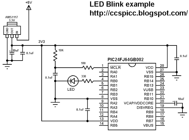
PIC24FJ64GB002 LED blink example circuit
The PIC24FJ64GB002 microcontroller works with 3.3V only and supply it we need a 3.3V source or a 5V source and AMS1117 3V3 voltage regulator.
The LED is connected to pin RB0 through 330 ohm resistor.
In this example the PIC24FJ64GB002 microcontroller runs with its internal oscillator.
PIC24FJ64GB002 LED Blink example C code:
The C code below was tested with CCS C compiler version 5.051.
In this example the LED blinks with a frequency of 1Hz (500ms ON and 500ms OFF ==> period = 1s).
// PIC24FJ64GB002 LED blink example CCS C code
// Internal oscillator used @ 8 MHz
// http://ccspicc.blogspot.com/
// electronnote@gmail.com

#include <24FJ64GB002.h>
#fuses FRC NOWDT NOJTAG OSCIO SOSC_IO
#use delay(clock = 8M)
#define LED PIN_B0                          // Led is connected to pin RB0

void main(){
  while(TRUE){
    output_toggle(LED);                     // Toggle led pin status
    delay_ms(500);                          // Wait 500 ms
  }
}

Sunday, September 24, 2017

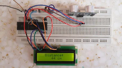
Distance meter using PIC16F887 and HC-SR04 ultrasonic sensor


This topic shows how to make a simple distance meter using PIC16F887 microcontroller and HC-SR04 ultrasonic sensor.
The HC-SR04 ultrasonic sensor can measure distances form 2cm to 400cm with an accuracy of 3mm. This sensor module includes ultrasonic transmitter, ultrasonic receiver and control circuit.
The HC-SR04 ultrasonic sensor has 4 pins as shown below where:
VCC : Positive power supply (+5V)
Trig : Trigger input pin
Echo : Echo output pin
GND : Ground (0V)
HC-SR04 Ultrasonic sensor pin out
HC-SR04 ultrasonic sensor timing diagram:
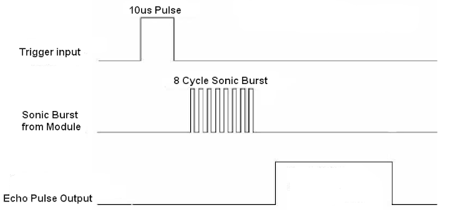
The timing diagram of the HC-SR04 ultrasonic sensor is shown below.
First we have to supply the sensor trigger pin with a pulse of 10µs and the sensor will automatically send 8 cycles burst of ultrasound at 40 kHz and raise its echo pin. The Echo is a distance object that is pulse width and the range in proportion. We can calculate the range through the time interval between sending trigger signal and receiving echo signal. Formula: uS / 58 = centimeters or uS / 148 =inch; or:
the range = high level time * sound velocity (340M/S) / 2.
HC-SR04 Ultrasonic sensor timing
Hardware Required:
  • PIC16F887 microcontroller
  • HC-SR04 ultrasonic sensor
  • 16x2 LCD screen
  • 10K variable resistor
  • +5V source
  • Breadboard
  • Jumper Wires
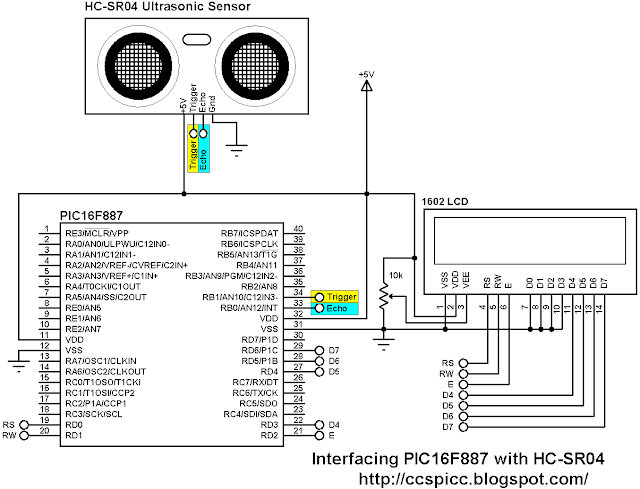
Distance meter using PIC16F887 and HC-SR04 ultrasonic sensor circuit:
Interfacing PIC16F887 with HC-SR04 ultrasonic sensor circuit diagram
In this project the PIC16F887 MCU runs with its internal oscillator and MCLR pin function is disabled.
Distance meter using PIC16F887 and HC-SR04 ultrasonic sensor C code:
The C code below was tested with CCS C compiler version 5.051.
The PIC16F887 runs with its internal oscillator @ 8MHz.
Basically I used Timer1 module to measure the pulse widths which comes from the Echo pin of the HC-SR04 sensor, the width of the pulse is related to the distance. Timer1 is configured to increment every 1us (prescaler = 2):
SETUP_TIMER_1(T1_INTERNAL | T1_DIV_BY_2);
First of all the MCU sends a pulse of 10 us to the sensor via pin RB1 which is the trigger pin of the sensor, then the MCU waits until the sensor raises its Echo pin (function wait_sensor() ). If the waiting time is higher than 990 us ==> time out and the function wait_sensor() returns 0.
if the function wait_sensor() returned 1, the microcontroller starts measuring the width of the Echo pin pulse (in us) using the function get_distance(), if the time > 24990 (distance > 400 cm) ==> out of range, otherwise the measured time will be converted to distance (in cm) by dividing it by 58.
No interrupt is used in this example.
The complete C code is below.
/*
  Distance meter using HC-SR04 ultrasonic sensor and PIC16F887 CCS C code.
  Echo and trigger pins of the HC-SR04 are connected to RB0 and RB1 respectively.
  http://ccspicc.blogspot.com/
  electronnote@gmail.com
*/

//LCD module connections
#define LCD_RS_PIN     PIN_D0
#define LCD_RW_PIN     PIN_D1
#define LCD_ENABLE_PIN PIN_D2
#define LCD_DATA4      PIN_D3
#define LCD_DATA5      PIN_D4
#define LCD_DATA6      PIN_D5
#define LCD_DATA7      PIN_D6
//End LCD module connections

#include <16F887.h>
#fuses INTRC_IO, NOMCLR, NOBROWNOUT, NOLVP
#use delay(clock = 8MHz)
#use fast_io(B)
#include <lcd.c>

int16 i, distance;
int1 wait_sensor(){
  i = 0;
  set_timer1(0);                                 // Reset Timer1
  while(!input(PIN_B0) && (i < 1000))
    i = get_timer1();                            // Read Timer1 and store its value in i
  if(i > 990)
    return 0;
  else
    return 1;
}
int16 get_distance(){
  i = 0;
  set_timer1(0);
  while(input(PIN_B0) && (i < 25000))
    i = get_timer1();
  return i;
}
void main(){
  setup_oscillator(OSC_8MHZ);                    // Set internal oscillator to 8MHz
  output_b(0);
  set_tris_b(1);                                 // Configure RB0 pin as input
  delay_ms(1000);
  lcd_init();                                    // Initialize LCD module
  lcd_putc('\f');                                // Clear LCD
  lcd_gotoxy(4, 1);                              // Go to column 4 row 1
  lcd_putc("Distance:");
  SETUP_TIMER_1(T1_INTERNAL | T1_DIV_BY_2);      // Configure Timer 1 to increment by 1 every 1 us
  while(TRUE){
    // Send 10us pulse to HC-SR04 Trigger pin
    output_high(PIN_B1);
    delay_us(10);
    output_low(PIN_B1);
    // Read pulse comes from HC-SR04 Echo pin
    if(wait_sensor()){
      distance = get_distance();
      if(distance > 24990){
        lcd_gotoxy(3, 2);                        // Go to column 3 row 2
        lcd_putc("Out Of Range");
      }
      else {
        distance = i/58;                         // Calculate the distance
        lcd_gotoxy(3, 2);                        // Go to column 3 row 2
        lcd_putc("       cm   ");
        lcd_gotoxy(6, 2);                        // Go to column 6 row 2
        printf(lcd_putc, "%3Lu", distance);
      }
    }
    else {
      lcd_gotoxy(3, 2);                          // Go to column 3 row 2
      lcd_putc("  Time Out  ");
    }
  delay_ms(100);
  }
}
// End of code
PIC16F887 MCU and HC-SR04 ultrasonic sensor hardware circuit

Wednesday, September 20, 2017

PIC16F887 projects


PIC16F887 microcontroller projects

Distance meter using PIC16F887 and HC-SR04 ultrasonic sensor

Wave audio player using PIC16F887 microcontroller

Real time clock and temperature monitor using PIC16F887 and DS3231

Read text files from FAT16 SD card with PIC16F887

MMC/SD Card raw data read with PIC16F887 microcontroller

UART Example for PIC16F887 microcontroller using CCS PIC C compiler

Sensorless brushless DC motor drive with an ESC and PIC16F887

RF Transmitter and receiver system using PIC16F887

Interfacing PIC16F887 with LM35 temperature sensor

RTOS Example with PIC16F887 microcontroller

CD-ROM Sensored brushless DC motor drive with PIC16F887 microcontroller

ST7735 TFT Display with PIC16F887 example

Two DC motors control with NEC IR remote control

Interfacing DS3231 with PIC16F887 microcontroller

Two motors control using PIC16F887 and L293D

NEC Protocol decoder with PIC16F887 microcontroller

RC5 Decoder with PIC16F887 microcontroller and CCS C compiler

DS1307 Interfacing with PIC16F887

Interfacing PIC16F887 with LM335 temperature sensor

PIC16F887 Microcontroller with DHT22 digital sensor

Interfacing PIC16F887 with DHT11 sensor

Interfacing PIC16F887 with LCD display

PIC16F887 Timers and Interrupts

LED Blink with PIC16F887 microcontroller

Monday, September 18, 2017

Wave audio player using PIC16F887 microcontroller


This small project shows how to make a simple wave audio player using PIC16F887 microcontroller and SD card. The WAV audio file used in this project is 8000 Hz, 8-bit stereo (2 channels).
Hardware Required:
  • PIC16F887 microcontroller
  • SD card (formatted with FAT16 or FAT32 file system)
  • ASM1117 3.3 voltage regulator
  • Audio amplifier (ex: PC speaker, LM386 ......)
  • Speaker
  • 20 MHz crystal oscillator
  • 2 x 22pF ceramic capacitors
  • 3 x 3.3K ohm resistor
  • 3 x 2.2K ohm resistor
  • 10K ohm resistor
  • 2 x 1K ohm resistor
  • 3 x 10uF polarized capacitor
  • 100nF ceramic capacitor
  • 5V Power source
  • Breadboard
  • Jumper wires
The Circuit:
The microcontroller generates audio using PWM technique, if the wave audio file is mono (1 channel) the microcontroller will generate only 1 PWM signal (PWM1) and hence we will hear the sound from 1 speaker only. If the wave audio file is stereo both speakers will give sound.
In this project the PIC16F887 runs with 20MHz crystal oscillator which is the maximum speed of this microcontroller, MCLR pin function is disabled.
The C code:
The C code below was tested with CCS C compiler versions 5.051.
In this project I used the FAT library (FAT16 and FAT32), its source file can be found in the the following topic:
SD card FAT library for CCS C compiler
I tested this project with FAT32 8 GB and FAT16 2 GB micro-SD cards.
The name of the wave audio file which I used was mywav (mywav.wav with the extension), its sample rate is 8000 Hz with 2 channels (stereo).
First of all I initialized the SD card using the function: sdcard_init(); this function return 0 if the initialization was OK and non-zero if there was an error. After the initialization of the SD card I initialized the FAT file system using the function fat_init(); and then I opened the wave audio file with the pre-selected name mywav.wav, all the three previous function returns 0 if OK and no-zero if error.
If the initialization of the SD card, the FAT system and opening of the file were OK that means the variable which named ok = 0 and playing the wave file starts using the function play(); .
To detect if the wave file is mono (1 channel) or stereo (2 channels), I read the byte 22 of the wave file using the function :
sdcard_read_byte(address_pointer + 22, &channel_count);
where the variable address_pointer belongs to the FAT library, this variable allows me to know the starting address of the wave audio file.
If the wave file is mono ==> channel_count =1 and if it is stereo ==> channel_count = 2.
I set the data buffer to 16 so each time the microcontroller reads 32 bytes from the SD card. The data buffer can be less or higher than 16.
The function fat_read_data(16, data) keeps reading file data from the SD card until it returns 1 which means end of the wave file is reached.
The wave file must be 8-bit and for that I configured the PWM outputs to give the maximum frequency with 8-bit resolution, for that I configured Timer2 module as shown below:
setup_timer_2(T2_DIV_BY_1, 63, 1);
The resolution of the PWM signal can be calculated using the function:
PWM Resolution = Log[(PR2 + 1)*4]/Log(2) = Log[(63 + 1)*4]/Log(2) = 8
The PWM frequency should be as higher as possible and with the previous configuration I got a PWM frequency of 78.125 KHz. It can be calculated with the function below:
PWM_Frequency = Fosc/[(PR2 + 1)*4*TMR2_Prescaler] = 20*10^6/[(63 + 1)*4*1] = 78.125 KHz.
If channel_count = 2 the 2nd PWM duty cycle also will be updated and the sound will be generated from PWM1 (RC2) and PWM2 (RC1) outputs (left and right).
Now how did I used Timer1 module and the wave file sample rate (8000 Hz):
the PWM duty cycles have to be updated every 125 us ( = 1/8000Hz), for that I used Timer1 to make the MCU waits for 125 us. In this example I didn't use Timer1 interrupt.
I configured Timer1 module to increment on every MCU cycle (0.2 us) and to compute Timer1 value (values between 2 updates) I used the function:
Fosc/[sample rate * 4) = 20 * 10^6/(8000 * 4) = 625
where sample rate = 18000 and Fosc = 20 * 10^6 .
In this example I used the value 500 instead of 625 because I got a slow audio streaming (i.e: some instructions are spent on loops).
The complete C code is the one below.
/*
  WAV Audio Player using PIC16F887 microcontroller and SD card CCS C code.
  FAT Library for CCS C compiler must be installed
  http://ccspicc.blogspot.com/
  electronnote@gmail.com
*/

// SD Card module connections
#define   SDCARD_SPI_HW
#define   SDCARD_PIN_SELECT  PIN_D3
// End SD card module connections

#include <16F887.h>
#fuses NOMCLR, HS, NOBROWNOUT, NOLVP
#use delay(clock = 20MHz)
#use fast_io(D)
#include <FAT_Lib.c>

const int8 *wav = "mywav.wav";
int1 ok = 0;
int8 i, j, data[16], channel_count;

void play(){
  sdcard_read_byte(address_pointer + 22, &channel_count);       // Read number of channels
  while(fat_read_data(16, data) == 0){
    for(i = 0; i < 16; i++){
      set_timer1(0);
      j = data[i];
      set_pwm1_duty((int16)j);                   // Update PWM1 duty cycle
      if(channel_count == 2){                    // If 2-channel wave file (stereo)
        i++;                                     // increment i
        j = data[i];
        set_pwm2_duty((int16)j);                 // Update PWM2 duty cycle
      }
      while(get_timer1() < 500);                 // Wait some time (about 125us) to update the duty cycles
    }
  }
}
void main(){
  delay_ms(2000);
  setup_ccp1(CCP_PWM);                           // Configure CCP1 as a PWM
  setup_ccp2(CCP_PWM);                           // Configure CCP2 as a PWM
  set_pwm1_duty(0);                              // set PWM1 duty cycle to 0
  set_pwm2_duty(0);                              // set PWM2 duty cycle to 0
  setup_timer_2(T2_DIV_BY_1, 63, 1);             // Set PWM frequency to maximum with 8-bit resolution
  setup_timer_1( T1_INTERNAL | T1_DIV_BY_1 );    // Timer1 configuration
  ok |= sdcard_init();                           // Initialize the SD card module
  ok |= fat_init();                              // Initialize FAT library
  ok |= fat_open_file(wav);                      // Open the wave file
  if(ok == 0){
    play();
  }
  set_pwm1_duty(0);                              // set PWM1 duty cycle to 0
  set_pwm2_duty(0);                              // set PWM2 duty cycle to 0
}   // End
The video below shows the result of the example except that the MCU used is PIC16F877A:


Sunday, September 17, 2017

WAV Player using PIC16F877A and SD card


This post shows how did I made a simple wave audio player using PIC16F877A microcontroller where the wave audio file is stored in 8 GB micro SD card.
The wave file which I used was 8000 Hz, 8-bit stereo (2 channels), I convert it from MP3 format to WAV format using a free and open source software named audacity (site: http://www.audacityteam.org/).
Hardware Required:
  • PIC16F877A microcontroller
  • SD card (formatted with FAT16 or FAT32)
  • ASM1117 3.3 voltage regulator
  • Audio amplifier (ex: PC speaker, LM386 ......)
  • Speaker
  • 20 MHz crystal oscillator
  • 2 x 22pF ceramic capacitors
  • 3 x 3.3K ohm resistor
  • 3 x 2.2K ohm resistor
  • 2 x 10K ohm resistor
  • 2 x 1K ohm resistor
  • 3 x 10uF polarized capacitor
  • 100nF ceramic capacitor
  • 5V Power source
  • Breadboard
  • Jumper wires

The Circuit:
WAV player using PIC16F877A and SD card circuit
The microcontroller generates audio using PWM technique, if the wave audio file is mono (1 channel) the microcontroller will generate only 1 PWM signal (PWM1) and hence we will hear the sound from 1 speaker only. If the wave audio file is stereo both speakers will give sound.
The C code:
The C code below was tested with CCS C compiler versions 5.051.
In this project I used the FAT library (FAT16 and FAT32), its source file can be found in the the following topic:
SD card FAT library for CCS C compiler
I tested this project with FAT32 8 GB and FAT16 2 GB micro-SD cards.
The name of the wave audio file which I used was mywav (mywav.wav with the extension), its sample rate is 8000 Hz with 2 channels (stereo).
First of all I initialized the SD card using the function: sdcard_init(); this function return 0 if the initialization was OK and non-zero if there was an error. After the initialization of the SD card I initialized the FAT file system using the function fat_init(); and then I opened the wave audio file with the pre-selected name mywav.wav, all the three previous function returns 0 if OK and no-zero if error.
If the initialization of the SD card, the FAT system and opening of the file were OK that means the variable which named ok = 0 and playing the wave file starts using the function play(); .
To detect if the wave file is mono (1 channel) or stereo (2 channels), I read the byte 22 of the wave file using the function :
sdcard_read_byte(address_pointer + 22, &channel_count);
where the variable address_pointer belongs to the FAT library, this variable allows me to know the starting address of the wave audio file.
If the wave file is mono ==> channel_count =1 and if it is stereo ==> channel_count = 2.
I set the data buffer to 16 so each time the microcontroller reads 32 bytes from the SD card. The data buffer can be less or higher than 16.
The function fat_read_data(16, data) keeps reading file data from the SD card until it returns 1 which means end of the wave file is reached.


The wave file must be 8-bit and for that I configured the PWM outputs to give the maximum frequency with 8-bit resolution, for that I configured Timer2 module as shown below:
setup_timer_2(T2_DIV_BY_1, 63, 1);
The resolution of the PWM signal can be calculated using the function:
PWM Resolution = Log[(PR2 + 1)*4]/Log(2) = Log[(63 + 1)*4]/Log(2) = 8
The PWM frequency should be as higher as possible and with the previous configuration I got a PWM frequency of 78.125 KHz. It can be calculated with the function below:
PWM_Frequency = Fosc/[(PR2 + 1)*4*TMR2_Prescaler] = 20*10^6/[(63 + 1)*4*1] = 78.125 KHz.
If channel_count = 2 the 2nd PWM duty cycle also will be updated and the sound will be generated from PWM1 (RC2) and PWM2 (RC1) outputs (left and right).
Now how did I used Timer1 module and the wave file sample rate (8000 Hz):
the PWM duty cycles have to be updated every 125 us ( = 1/8000Hz), for that I used Timer1 to make the MCU waits for 125 us. In this example I didn't use Timer1 interrupt.
I configured Timer1 module to increment on every MCU cycle (0.2 us) and to compute Timer1 value (values between 2 updates) I used the function:
Fosc/[sample rate * 4) = 20 * 10^6/(8000 * 4) = 625
where sample rate = 18000 and Fosc = 20 * 10^6 .
In this example I used the value 500 instead of 625 because I got a slow audio streaming (i.e: some instructions are spent on loops).
The complete C code is the one below.
/*
  WAV Player using PIC16F877A microcontroller and SD card CCS C code.
  http://ccspicc.blogspot.com/
  electronnote@gmail.com
*/

// SD Card module connections
#define   SDCARD_SPI_HW
#define   SDCARD_PIN_SELECT  PIN_D3
// End SD card module connections

#include <16F877A.h>
#fuses HS,NOWDT,NOPROTECT,NOLVP                       
#use delay(clock = 20MHz)
#use fast_io(D)
#include <FAT_Lib.c>

const int8 *wav = "mywav.wav";
int1 ok = 0;
int8 i, j, data[16], channel_count;

void play(){
  sdcard_read_byte(address_pointer + 22, &channel_count);       // Read number of channels
  while(fat_read_data(16, data) == 0){
    for(i = 0; i < 16; i++){
      set_timer1(0);
      j = data[i];
      set_pwm1_duty((int16)j);                   // Update PWM1 duty cycle
      if(channel_count == 2){                    // If 2-channel wave file (stereo)
        i++;                                     // increment i
        j = data[i];
        set_pwm2_duty((int16)j);                 // Update PWM2 duty cycle
      }
      while(get_timer1() < 500);                 // Wait some time (about 125us) to update the duty cycles
    }
  }
}
void main(){
  delay_ms(2000);
  setup_ccp1(CCP_PWM);                           // Configure CCP1 as a PWM
  setup_ccp2(CCP_PWM);                           // Configure CCP2 as a PWM
  set_pwm1_duty(0);                              // set PWM1 duty cycle to 0
  set_pwm2_duty(0);                              // set PWM2 duty cycle to 0
  setup_timer_2(T2_DIV_BY_1, 63, 1);             // Set PWM frequency to maximum with 8-bit resolution
  setup_timer_1( T1_INTERNAL | T1_DIV_BY_1 );
  ok |= sdcard_init();                           // Initialize the SD card module
  ok |= fat_init();                              // Initialize FAT library
  ok |= fat_open_file(wav);                      // Open the wave file
  if(ok == 0){
    play();
  }
  set_pwm1_duty(0);                              // set PWM1 duty cycle to 0
  set_pwm2_duty(0);                              // set PWM2 duty cycle to 0
}   // End
Wave player using PIC16F877A microcontroller and SD card video:


Saturday, September 16, 2017

PIC12F1822 + DS3231 + Remote Control


PIC12F1822 is a small microcontroller has only 8 pins which is not enough for building a real time clock using DS3231 with set buttons because the DS3231 needs 2 pins and the LCD screen needs 3 pins, therefore I've only 1 free pin. I connected that pin to an IR receiver and I used a remote control with a lot of buttons where I used only 3 buttons and the problem solved.
This post shows how did I build a simple real time clock using PIC12F1822, 1602 LCD and DS3231 with Car MP3 IR remote control (NEC protocol RC).
Before this project I made a NEC remote control decoder using PIC12F1822 MCU:
Extended NEC Protocol Decoder Using PIC12F1822 Microcontroller
Time and calendar are displayed on 1602 LCD with the help of a serial-in parallel-out shift register (74HC595, 74HC164, CD4094 .....) as what I made in the example below:
Interfacing PIC12F1822 microcontroller with LCD display
The DS3231 uses I2C protocol to interface with the master device which is in our example the PIC12F1822 MCU which has one I2C module.
The I2C protocol uses only two lines: SCL (Serial Clock) and SDA (Serial Data) which are in the PIC12F1822 pin RA1 and pin RA2 respectively.
Hardware Required:
  • PIC12F1822 microcontroller
  • DS3231 board - datasheet
  • 1602 LCD screen
  • 74HC595 shift register (74HC164 and CD4094 can be used)
  • IR receiver
  • 10K ohm variable resistor
  • 47uF capacitor
  • 5V supply source
  • Breadboard
  • Jumper wires
 The Circuit:
PIC12F1822 + DS3231 + Car MP3 remote control circuit
The IR receiver has 3 pins: GND, VCC and OUT. Pin OUT is connected to pin RA3 of the PIC12F1822.
The LCD screen with the 74HC595 shift register are connected to pins: RA0 (Enable), RA4 (Data) and RA5 (Clock).
The DS3231 board SCL and SDA are connected to pins RA1 and RA2 respectively.
In this project the PIC12F1822 uses its internal oscillator and MCLR pin is configured as a digital pin.
The Code:
The C code below was tested with CCS C compiler version 5.051.
The hardware I2C module of the PIC12F1822 MCU is initialized and configured using the function below with a speed of 100KHz:
#use I2C(master, I2C1, FAST = 100000)
master: set the microcontroller to the master mode
I2C1: use first I2C module.
The DS3231 works with BCD format only and to convert the BCD to decimal and vise versa I used the 2 functions below. Before displaying (after reading from DS3231), the data have to be converted from BCD to decimal, and before writing to the DS3231 (after editing the parameters) the data have to be converted from decimal to BCD:
int8 bcd_to_decimal(number)
int8 decimal_to_bcd(number)
Each function returns the converted value of the variable number.
void DS3231_display() : displays time and calendar data, before displaying time and calendar data are converted from BCD format to decimal format using the function bcd_to_decimal(number) .
int8 edit(x, y, parameter) : I used this function to edit time calendar parameters (minutes, hours, date, month and year). I used a variable named i to distinguish between the parameters:
i = 0, 1 : time hours and minutes respectively
i = 2, 3, 4: calendar date, month and year respectively
After the edit of time and calendar, the data have to be converted back to BCD format using the function decimal_to_bcd(number) and written back to the DS3231.
void blink() : this small function works as a delay except that it is interrupted by the IR remote control codes for buttons 1, 2 and 3. When called and without pressing any of the three button the total time is 10 x 25ms = 250ms. With this function we can see the blinking of the selected parameter with a frequency of 2Hz. So a delay of 250ms comes after the print of the selected parameter and after that delay a 2 spaces is printed which makes the parameter disappears from the LCD and another 250ms delay comes after the print of the 2 spaces.
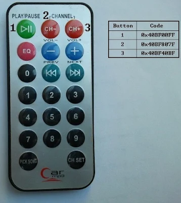
The remote control buttons and their codes are shown in the image below:
Car MP3 IR remote control button codes 
I used only 3 buttons where button 1 selects the parameter which we want to set (hours, minutes, date, month or year). Button 2 increments the selected parameter and button 3 decrements it. The rest of buttons have no effect on the circuit.
Finally the interfacing of the LCD with the PIC12F1822 needs a small driver which can be found in the the following topic:
3-Wire LCD driver for CCS PIC C compiler
The complete C code is the one below.
/* Interfacing PIC12F1822 MCU with DS3231 with NEC IR remote control (Car MP3)
   http://ccspicc.blogspot.com/
   electronnote@gmail.com
*/

//LCD module connections
#define LCD_DATA_PIN  PIN_A5
#define LCD_CLOCK_PIN PIN_A4
#define LCD_EN_PIN    PIN_A0
//End LCD module connections

#include <12F1822.h>
#fuses NOMCLR INTRC_IO PLL_SW
#use delay(clock=32000000)
#use fast_io(A)
#include <3WireLCD.c>                            // 3-Wire LCD driver source file
#define IR_Sensor PIN_A3
#use I2C(master, I2C1, FAST = 100000)

int1  nec_ok = 0;
int8  i, second, minute, hour, date, month, year;
int32 nec_code;
void nec_remote_read(){
  int8 j;
  int16 count = 0;
  // Check 9ms pulse (remote control sends logic high)
  while(!input(IR_Sensor) && (count < 9500))
    count = GET_TIMER1();
  if((count > 9499) || (count < 8500))
    return;
  // Check 4.5ms space (remote control sends logic low)
  SET_TIMER1(0);
  count = 0;
  while((input(IR_Sensor)) && (count < 5000))
    count = GET_TIMER1();
  if((count > 4999) || (count < 1500))
    return;
  if(count < 3000){                              // Check if previous code is repeated
    SET_TIMER1(0);
    count = 0;
    while(!input(IR_Sensor) && (count < 650))
      count = GET_TIMER1();
    if((count > 649) || (count < 500))
      return;
    // Check if the repeated code is for button 2 or 3
    if((nec_code == 0x40BF807F || nec_code == 0x40BF40BF)){
      nec_ok = 1;                                // Decoding process is finished with success
      disable_interrupts(INT_RA3);               // Disable the external interrupt
      return;
    }
  }
  // Read message (32 bits)
  for(j = 0; j < 32; j++){
    SET_TIMER1(0);
    count = 0;
    while(!input(IR_Sensor) && (count < 650))
      count = GET_TIMER1();
    if((count > 649) || (count < 500))
      return;
    count = 0;
    SET_TIMER1(0);
    while((input(IR_Sensor)) && (count < 1800))
      count = GET_TIMER1();
    if( (count > 1799) || (count < 400))
      return;
    if( count > 1000)                            // If space width > 1ms
      bit_set(nec_code, (31 - j));               // Write 1 to bit (31 - j)
    else                                         // If space width < 1ms
      bit_clear(nec_code, (31 - j));             // Write 0 to bit (31 - j)
  }
  disable_interrupts(INT_RA3);
  nec_ok = 1;
  return;
}
#INT_RA                                          // RA port interrupt on change
void ra_isr(void){
  SET_TIMER1(0);
  SETUP_TIMER_1(T1_INTERNAL | T1_DIV_BY_8);      // Configure Timer 1 to increment every 1 us  
  nec_remote_read();
  SETUP_TIMER_1(T1_DISABLED);                    // Stop Timer1 module
  clear_interrupt(INT_RA);
}
int8 bcd_to_decimal(number){                     // Convert BCD to decimal function
  return((number >> 4) * 10 + (number & 0x0F));
}
int8 decimal_to_bcd(number){                     // Convert decimal to BCD function
  return(((number / 10) << 4) + (number % 10));
}
void ds3231_display(){
  // Convert data from BCD format to decimal format
  second = bcd_to_decimal(second);
  minute = bcd_to_decimal(minute);
  hour   = bcd_to_decimal(hour);
  date   = bcd_to_decimal(date);
  month  = bcd_to_decimal(month);
  year   = bcd_to_decimal(year);
  // End conversion
  lcd_goto(13, 1);   
  printf(lcd_out,"%02u", second);                // Display seconds
  lcd_goto(10, 1);   
  printf(lcd_out,"%02u", minute);                // Display minutes
  lcd_goto(7, 1);   
  printf(lcd_out,"%02u", hour);                  // Display hours
  lcd_goto(7, 2);   
  printf(lcd_out,"%02u", date);                  // Display date
  lcd_goto(10, 2);   
  printf(lcd_out,"%02u", month);                 // Display month
  lcd_goto(15, 2);   
  printf(lcd_out,"%02u", year);                  // Display year
}
void _reset(){
  nec_ok = 0;                                    // Reset decoding process
  enable_interrupts(INT_RA3_H2L);                // Enable RA3 interrupt (High to low)
}
void blink(){
  int8 j = 0;
  while((!nec_ok || (nec_code != 0x40BF00FF) && (nec_code != 0x40BF40BF) && (nec_code != 0x40BF807F)) && (j < 10)){
    j++;
    delay_ms(25);
  }
}
int8 edit(x, y, parameter){
  _reset();
  while(TRUE){
    if(nec_ok && nec_code == 0x40BF40BF){        // If button RB1 is pressed
      parameter++;
      if(i == 0 && parameter > 23)               // If hours > 23 ==> hours = 0
        parameter = 0;
      if(i == 1 && parameter > 59)               // If minutes > 59 ==> minutes = 0
        parameter = 0;
      if(i == 2 && parameter > 31)               // If date > 31 ==> date = 1
        parameter = 1;
      if(i == 3 && parameter > 12)               // If month > 12 ==> month = 1
        parameter = 1;
      if(i == 4 && parameter > 99)               // If year > 99 ==> year = 0
        parameter = 0;
    }
    if(nec_ok && nec_code == 0x40BF807F){
      if(i == 0 && parameter < 1)
        parameter = 24;
      if(i == 1 && parameter < 1)
        parameter = 60;
      if(i == 2 && parameter < 2)
        parameter = 32;
      if(i == 3 && parameter < 2)
        parameter = 13;
      if(i == 4 && parameter < 1)
        parameter = 100;
      parameter--;
    }
    lcd_goto(x, y);
    printf(lcd_out,"%02u", parameter);
    if(nec_ok){
      delay_ms(200);
      _reset();
    }
    blink();
    lcd_goto(x, y);
    lcd_out("  ");                              // Display two spaces
    blink();
    if(nec_ok && nec_code == 0x40BF00FF){
      lcd_goto(x, y);
      printf(lcd_out,"%02u", parameter);
      i++;                                       // Increment 'i' for the next parameter
      return parameter;                          // Return parameter value and exit
    }
  }
}
void main() {
  setup_oscillator(OSC_8MHZ | OSC_PLL_ON);       // Set internal oscillator to 32MHz (8MHz and PLL)
  set_tris_a(0x0E);                              // Configure RA1, RA2 & RA3 as inputs
  port_a_pullups(8);                             // Enable pin RA3 internal pull-up
  lcd_initialize();                              // Initialize LCD module
  lcd_cmd(LCD_CLEAR);                            // LCD Clear
  enable_interrupts(GLOBAL);                     // Enable global interrupts
  clear_interrupt(INT_RA);                       // Clear RA IOC flag bit
  enable_interrupts(INT_RA3_H2L);                // Enable RA3 interrupt (High to low)
  lcd_goto(1, 1);  lcd_out("TIME:   :  :");
  lcd_goto(1, 2);  lcd_out("DATE:   /  /20");
  while(TRUE){
    if(nec_ok == 1){                             // If a NEC remote code was received
      if(nec_code == 0x40BF00FF){                // If the remote code is for button 1
        i = 0;
        hour   = edit(7, 1, hour);
        minute = edit(10, 1, minute);
        date   = edit(7, 2, date);
        month  = edit(10, 2, month);
        year   = edit(15, 2, year);
        // Convert decimal to BCD
        minute = decimal_to_bcd(minute);
        hour   = decimal_to_bcd(hour);
        date   = decimal_to_bcd(date);
        month  = decimal_to_bcd(month);
        year   = decimal_to_bcd(year);
        // End conversion
        // Write data to DS3231 RTC
        i2c_start();                             // Start I2C protocol
        i2c_write(0xD0);                         // DS3231 address
        i2c_write(0);                            // Send register address
        i2c_write(0);                            // Reset seconds and start oscillator
        i2c_write(minute);                       // Write minute value to DS3231
        i2c_write(hour);                         // Write hour value to DS3231
        i2c_write(1);                            // Write day value (not used)
        i2c_write(date);                         // Write date value to DS3231
        i2c_write(month);                        // Write month value to DS3231
        i2c_write(year);                         // Write year value to DS3231
      }
      _reset();                                  // Call _reset function
    }
    i2c_start();                                 // Start I2C protocol
    i2c_write(0xD0);                             // DS3231 address
    i2c_write(0);                                // Send register address
    i2c_start();                                 // Restart I2C
    i2c_write(0xD1);                             // Initialize data read
    second = i2c_read(1);                        // Read seconds from register 0
    minute = i2c_read(1);                        // Read minutes from register 1
    hour   = i2c_read(1);                        // Read hour from register 2
    i2c_read(1);                                 // Read day from register 3 (not used)
    date   = i2c_read(1);                        // Read date from register 4
    month  = i2c_read(1);                        // Read month from register 5
    year   = i2c_read(0);                        // Read year from register 6
    i2c_stop();                                  // Stop I2C protocol
    DS3231_display();                            // Display time & calendar
    delay_ms(50);
  }
}
// End of code.
Small video: