Friday, September 8, 2017

Interfacing PIC12F1822 with 1602 LCD and LM35 temperature sensor


This post shows a simple interfacing of PIC16F1822 microcontroller with 16x2 LCD and LM35 analog temperature sensor.
The LM35 temperature sensor is a three pin device (VCC, OUT and GND) with an output voltage linearly related to Centigrade temperature. Since the LM35 output varies with dependent to the temperature we need ADC (Analog-to-Digital Converter) module to measure this voltage.
The LM35 output has linear +10mV/°C scale factor means the following:
If the output voltage =   10mV ---> temperature =   1°C
If the output voltage = 100mV ---> temperature = 10°C
If the output voltage = 200mV ---> temperature = 20°C
If the output voltage = 370mV ---> temperature = 37°C
and so on.
LM35 Futures (from datasheet):
  • Calibrated Directly in ° Celsius (Centigrade)
  • Linear + 10 mV/°C Scale Factor
  • 0.5°C Ensured Accuracy (at +25°C)
  • Rated for Full −55°C to +150°C Range
  • Suitable for Remote Applications
  • Low Cost Due to Wafer-Level Trimming
  • Operates from 4 to 30 V
  • Less than 60-μA Current Drain
  • Low Self-Heating, 0.08°C in Still Air
  • Nonlinearity Only ±¼°C Typical
  • Low Impedance Output, 0.1 Ω for 1 mA Load
The ADC module converts analog data into digital data. The PIC12F1822 MCU has a 10-bit ADC module and a built-in fixed voltage reference (FVR) which makes it a good choice for this application. With the fixed voltage reference we get approximately an exact result. Normally negative and positive references of the ADC module are VSS and VDD respectively, but VDD is not exactly equal to 5.00V and here we should use the fixed voltage reference as a positive reference of the ADC module.
The PIC12F1822 has 3 fixed voltage references: 1.024V, 2.048V and 4.096V. For example if we set the fixed voltage reference to 4.096V and the ADC module is configured so that the negative and the positive references are VSS and FVR (Fixed Voltage Reference) respectively, in this case the equivalent 10-bit digital value of 4.096 is 1023 and 3.00V is 3.00 * 1023/4.096 = 749 , and so on.
In this project I used FVR = 1.024V because the LM35 output is generally less than 1V and also it gave me better result (let's say higher resolution). Now the ADC module works in the interval between 0 and 1.024V.
The temperature value is displayed on 1602 LCD display. This LCD is interfaced with the microcontroller using 74HC595 (74HC164 .....) shift register as what was done in this post:
Interfacing PIC12F1822 microcontroller with LCD display
Hardware Required:
  • PIC12F1822 microcontroller
  • LM35 temperature sensor  -- datasheet
  • 1602 LCD screen
  • 74HC595 shift register
  • 10K ohm variable resistor
  • Breadboard
  • 5V voltage source
  • Jumper wires
Interfacing PIC12F1822 with LM35 sensor circuit:
Interfacing PIC12F1822 microcontroller with LM35 sensor circuit
The output of the LM35 temperature sensor is connected to analog channel 0 (RA0) of the PIC12F1822 microcontroller.
The 1602 LCD display pins are connected to 74HC595 shift register except the Enable pin (E) which is connected directly to the PIC12F1822 MCU. With the help of the shift register 74HC595, the LCD uses only 3 data lines: clock, data and enable. Other types of serial-in parallel-out shift registers can be used such as 74HC164 and CD4094 (74HC4094).
In this example the PIC12F1822 MCU uses its internal oscillator and MCLR pin function is disabled.
Interfacing PIC12F1822 with LM35 temperature sensor C code:
The C code below was tested with CCS PIC C compiler version 5.051.
Reading voltage quantity using the ADC gives us a number between 0 and 1023 (10-bit resolution), 0V is represented by 0 and 1.024V is represented by 1023 (ADC positive reference comes from FVR which is set to 1.024V) . Converting back the ADC digital value is easy, we can use the following equation for that conversion:
Voltage (in Volts) = ADC reading * 1.024 / 1024
Multiplying the previous result by 100 (LM35 scale factor is 10mV/°C = 0.01V/°C) will gives the actual temperature:
Temperature(°C) = ADC reading * 0.1
where 0.1 = 100 * 1.024 / 1024
The complete C code is the one below.
/* Interfacing PIC12F1822 with LM35 temperature sensor C code.
   The temperature result is displayed on 1602 LCD screen with
   the help of a shift register (74HC595, 74HC164 ....).
   Serial LCD driver for CCS C must be added to the project.
   http://ccspicc.blogspot.com/
   electronnote@gmail.com
*/

// Serial LCD module connections
#define LCD_DATA_PIN  PIN_A5
#define LCD_CLOCK_PIN PIN_A4
#define LCD_EN_PIN    PIN_A2
// End serial LCD module connections

#include <12F1822.h>
#device ADC = 10
#fuses NOMCLR INTRC_IO PLL_SW
#use delay(clock=32000000)
#use fast_io(A)
#include <3WireLCD.c>                            // 3-wire serial LCD driver source file

float temp;
void main() {
  setup_oscillator(OSC_8MHZ | OSC_PLL_ON);       // Set internal oscillator to 8MHz with PLL enabled (32MHz)
  lcd_initialize();                              // Initialize LCD module
  lcd_cmd(LCD_CLEAR);                            // LCD Clear
  setup_vref(VREF_ADC_1v024);                    // Configure FVR to supply ADC positive reference with 1.024V
  setup_adc(ADC_CLOCK_INTERNAL);                 // ADC Module uses its internal oscillator
  setup_adc_ports(sAN0 | VSS_FVR);               // Configure AN0 pin as analog - Voltage reference: VSS - FVR(1.024V)
  set_adc_channel(0);                            // Select channel 0 (AN0)
  lcd_goto(3, 1);                                // Go to column 3 row 1
  printf(lcd_out, "Temperature:");
 while(TRUE){
    delay_ms(1000);
    temp = read_adc() * 0.1;                     // Read analog voltage and convert it to Kelvin (0.1 = 100*1.024/1024)
    lcd_goto(6, 2);                              // Go to column 6 row 2
    printf(lcd_out, "%4.1fßC", temp);            // Display LM35 temperature result (float format)
  }
}
The Result:
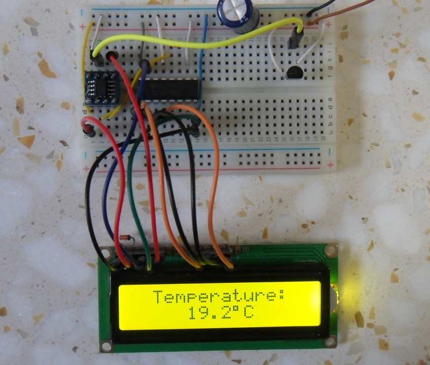
PIC12F1822 with LM35 temperature sensor hardware circuit

Sunday, September 3, 2017

Interfacing LM35 temperature sensor with PIC18F4550 microcontroller


Interfacing PIC18F4550 with LM35
This small topic shows the circuit diagram and CCS C code of the interfacing of LM35 temperature sensor with PIC18F4550 microcontroller.
The LM35 temperature sensor is three pin device (VCC, OUT and GND) with an output voltage linearly related to Centigrade temperature. Since the LM35 output varies with dependent to the temperature we need ADC (Analog-to-Digital Converter) module to measure this voltage. The ADC module converts analog data into digital data.
The LM35 output has linear +10mV/°C scale factor means the following:
If the output voltage =   10mV ---> temperature =   1°C
If the output voltage = 100mV ---> temperature = 10°C
If the output voltage = 200mV ---> temperature = 20°C
If the output voltage = 370mV ---> temperature = 37°C
and so on.
LM35 Futures (from datasheet):
  • Calibrated Directly in ° Celsius (Centigrade)
  • Linear + 10 mV/°C Scale Factor
  • 0.5°C Ensured Accuracy (at +25°C)
  • Rated for Full −55°C to +150°C Range
  • Suitable for Remote Applications
  • Low Cost Due to Wafer-Level Trimming
  • Operates from 4 to 30 V
  • Less than 60-μA Current Drain
  • Low Self-Heating, 0.08°C in Still Air
  • Nonlinearity Only ±¼°C Typical
  • Low Impedance Output, 0.1 Ω for 1 mA Load
Hardware Required:
  • PIC18F4550 microcontroller
  • LM35 temperature sensor  -- datasheet
  • 1602 LCD screen
  • 10K ohm variable resistor
  • Breadboard
  • 5V voltage source
  • Jumper wires
Interfacing PIC18F4550 with LM35 sensor circuit:
Interfacing PIC18F4550 with LM35 temperature sensor circuit
The output of the LM35 temperature sensor is connected to analog channel 0 (AN0) of the PIC18F4550 microcontroller.
In this example the MCU uses its internal oscillator and MCLR pin function is disabled.
Interfacing PIC18F4550 with LM35 temperature sensor C code:
The C code below was tested with CCS PIC C compiler version 5.051.
Reading voltage quantity using the ADC gives us a number between 0 and 1023 (10-bit resolution), 0V is represented by 0 and 5V is represented by 1023. Converting back the ADC digital value is easy and we can use the following equation for that conversion:
Voltage (in Volts) = ADC reading * 5 / 1023
Multiplying the previous result by 100 (LM35 scale factor is 10mV/°C = 0.01V/°C) will gives the actual temperature:
Temperature(°C) = ADC reading * 0.489
where 0.489 = 500 / 1023
The complete C code is the one below.
/* Interfacing PIC18F4550 with LM35 analog temperature sensor CCS C code.
   Read LM35 datasheet to understand the code!
   http://ccspicc.blogspot.com/
   electronnote@gmail.com
*/

//LCD module connections
#define LCD_RS_PIN      PIN_D0
#define LCD_RW_PIN      PIN_D1
#define LCD_ENABLE_PIN  PIN_D2
#define LCD_DATA4       PIN_D3
#define LCD_DATA5       PIN_D4
#define LCD_DATA6       PIN_D5
#define LCD_DATA7       PIN_D6
//End LCD module connections

#include <18F4550.h>
#fuses NOMCLR, INTRC_IO
#device ADC=10
#use delay(clock = 8MHz)
#include <lcd.c>

char temperature[] = " 00.0 C";
unsigned int16 temp;
void main(){
  setup_oscillator(OSC_8MHZ);                    // Set internal oscillator to 8MHz
  setup_adc(ADC_CLOCK_INTERNAL);                 // ADC Module uses its internal oscillator
  setup_adc_ports(AN0);                          // Configure AN0 pin as analog
  set_adc_channel(0);                            // Select channel 0 (AN0)
  lcd_init();                                    // Initialize LCD module
  lcd_putc('\f');                                // Clear LCD
  lcd_gotoxy(3, 1);                              // Go to column 3 row 1
  printf(lcd_putc, "Temperature:");
  temperature[5]  = 223;                         // Put degree symbol (°)
  while(TRUE){
    delay_ms(1000);
    temp = read_adc() * 0.489;                   // Read analog voltage and convert it to degree celsius (0.489 = 500/1023)
    if (temp > 99)
      temperature[0]  = 1 + 48;                  // Put 1 (of hundred)
    else
      temperature[0]  = ' ';                     // Put space
    temperature[1]  = (temp / 10) % 10  + 48;
    temperature[2]  =  temp % 10  + 48;
    lcd_gotoxy(5, 2);                            // Go to column 5 row 2
    printf(lcd_putc, temperature);               // Display LM35 temperature result
  }
}
The result:
PIC18F4550 with LM35 temperature sensor hardware circuit

Monday, August 28, 2017

Interfacing PIC16F877A with LM35 temperature sensor


The LM35 temperature sensor is three pin device (VCC, OUT and GND) with an output voltage linearly related to Centigrade temperature. Since the LM35 output varies with dependent to the temperature we need ADC (Analog-to-Digital Converter) module to measure this voltage. The ADC module converts analog data into digital data.
The LM35 output has linear +10mV/°C scale factor means the following:
If the output voltage =   10mV ---> temperature =   1°C
If the output voltage = 100mV ---> temperature = 10°C
If the output voltage = 200mV ---> temperature = 20°C
If the output voltage = 370mV ---> temperature = 37°C
and so on.
LM35 Futures (from datasheet):
  • Calibrated Directly in ° Celsius (Centigrade)
  • Linear + 10 mV/°C Scale Factor
  • 0.5°C Ensured Accuracy (at +25°C)
  • Rated for Full −55°C to +150°C Range
  • Suitable for Remote Applications
  • Low Cost Due to Wafer-Level Trimming
  • Operates from 4 to 30 V
  • Less than 60-μA Current Drain
  • Low Self-Heating, 0.08°C in Still Air
  • Nonlinearity Only ±¼°C Typical
  • Low Impedance Output, 0.1 Ω for 1 mA Load
This topic shows how to interface the microcontroller PIC16F877A with LM35 analog temperature sensor.
Hardware Required:
  • PIC16F877A microcontroller
  • LM35 temperature sensor  -- datasheet
  • 1602 LCD screen
  • 8MHz crystal
  • 2 x 22pF ceramic capacitor
  • 10K ohm variable resistor
  • Breadboard
  • 5V voltage source
  • Jumper wires
Interfacing PIC16F877A with LM35 sensor circuit:
PIC16F877A with LM35 temperature sensor circuit
The output of the LM35 temperature sensor is connected to analog channel 0 (AN0) of the PIC16F877A.
In this example the microcontroller runs with crystal oscillator @ 8MHz.
Interfacing PIC16F877A with LM35 temperature sensor C code:
The C code below was tested with CCS PIC C compiler version 5.051.
Reading voltage quantity using the ADC gives us a number between 0 and 1023 (10-bit resolution), 0V is represented by 0 and 5V is represented by 1023. Converting back the ADC digital value is easy and we can use the following equation for that conversion:
Voltage (in Volts) = ADC reading * 5 / 1023
Multiplying the previous result by 100 (LM35 scale factor is 10mV/°C = 0.01V/°C) will gives the actual temperature:
Temperature(°C) = ADC reading * 0.489
where 0.489 = 500 / 1023
/* Interfacing PIC16F877A with LM35 analog temperature sensor CCS C code.
   Read LM35 datasheet to understand the code!
   http://ccspicc.blogspot.com/
   electronnote@gmail.com
*/

//LCD module connections
#define LCD_RS_PIN      PIN_D0
#define LCD_RW_PIN      PIN_D1
#define LCD_ENABLE_PIN  PIN_D2
#define LCD_DATA4       PIN_D3
#define LCD_DATA5       PIN_D4
#define LCD_DATA6       PIN_D5
#define LCD_DATA7       PIN_D6
//End LCD module connections

#include <16F877A.h>
#fuses HS,NOWDT,NOPROTECT,NOLVP
#device ADC=10
#use delay(clock = 8MHz)
#include <lcd.c>

char temperature[] = " 00.0 C";
unsigned int16 temp;
void main(){
  setup_adc(ADC_CLOCK_INTERNAL);                 // ADC Module uses its internal oscillator
  setup_adc_ports(AN0);                          // Configure AN0 pin as analog
  set_adc_channel(0);                            // Select channel 0 (AN0)
  lcd_init();                                    // Initialize LCD module
  lcd_putc('\f');                                // Clear LCD
  lcd_gotoxy(3, 1);                              // Go to column 3 row 1
  printf(lcd_putc, "Temperature:");
  while(TRUE){
    delay_ms(1000);
    temp = read_adc() * 0.489;                   // Read analog voltage and convert it to degree celsius (0.489 = 500/1023)
    if (temp > 99)
      temperature[0]  = 1 + 48;                  // Put 1 (of hundred)
    else
      temperature[0]  = ' ';                     // Put space
    temperature[1]  = (temp / 10) % 10  + 48;
    temperature[2]  =  temp % 10  + 48;
    temperature[5] = 223;                        // Degree symbol
    lcd_gotoxy(5, 2);                            // Go to column 5 row 2
    printf(lcd_putc, temperature);               // Display LM35 temperature result
  }
}
Interfacing PIC16F877A with LM35 videos:
The video below shows a simple hardware circuit of our example.


And the following video shows the simulation.


PIC16F877A + LM35 Proteus simulation file download

Wednesday, August 2, 2017

Interfacing PIC16F887 with LM35 temperature sensor


PIC16F887 with LM35 sensor hardware circuit 
A thermometer can easily be implemented using the low cost analog temperature sensor LM35. The LM35 temperature sensor is three pin device (VCC, OUT and GND) with an output voltage linearly related to Centigrade temperature. Since the LM35 output varies with dependent to the temperature we need ADC (Analog-to-Digital Converter) module to measure this voltage. The ADC module converts analog data into digital data.
The LM35 output has linear +10mV/°C scale factor means the following:
If the output voltage =   10mV ---> temperature =   1°C
If the output voltage = 100mV ---> temperature = 10°C
If the output voltage = 200mV ---> temperature = 20°C
If the output voltage = 370mV ---> temperature = 37°C
and so on.
This article shows the interfacing of the LM35 temperature sensor with PIC16F887 microcontroller.
The PIC16F887 microcontroller has one 10-bit ADC module with up to 14 channels. In this example one channel for the LM35 output is needed.
Hardware Required:
  • PIC16F887 microcontroller
  • LM35 temperature sensor  -- datasheet
  • 16x2 LCD screen
  • 10K ohm variable resistor
  • Breadboard
  • 5V voltage source
  • Jumper wires
Interfacing PIC16F887 with LM35 temperature sensor circuit:
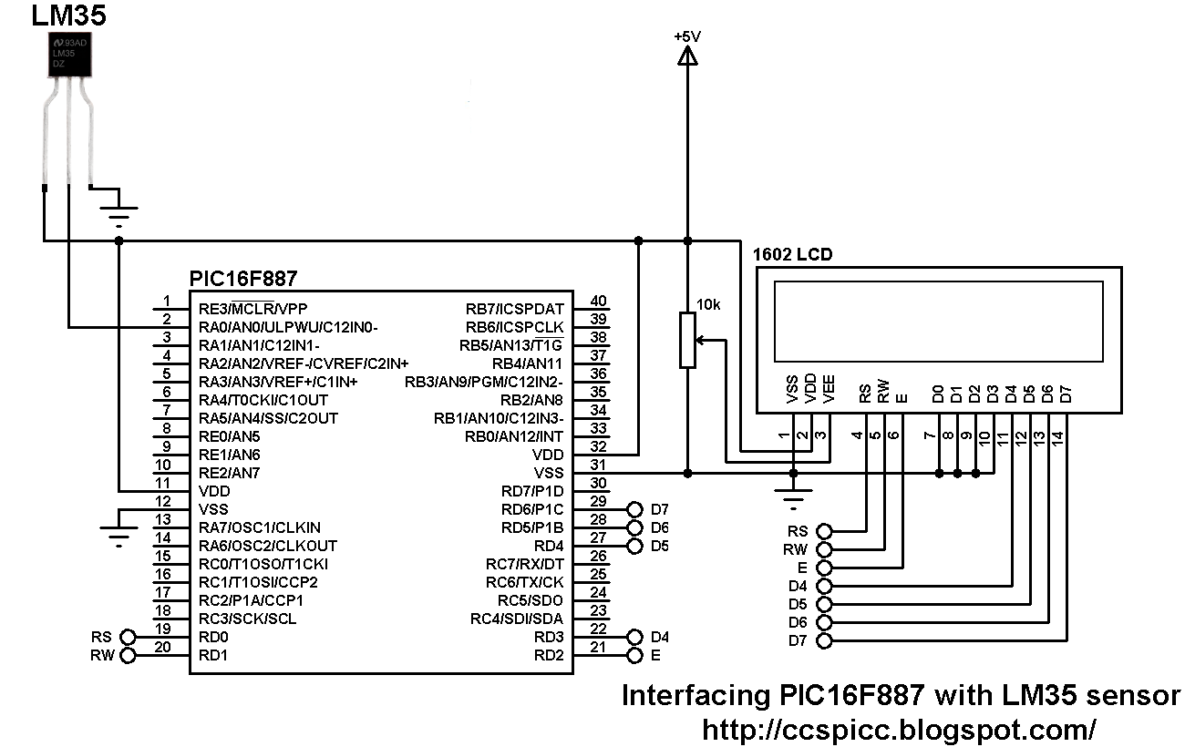
Interfacing PIC16F887 with LM35 temperature sensor circuit diagram
In this project the PIC16F887 microcontroller uses its internal oscillator which is set in the C code and MCLR pin function is disabled.
Interfacing PIC16F887 with LM35 temperature sensor CCS C code:
Reading voltage quantity using the ADC gives us a number between 0 and 1023 (10-bit resolution), 0V is represented by 0 and 5V is represented by 1023. Converting back the ADC digital value is easy and we can use the following equation for that conversion:
Voltage (in Volts) = ADC reading * 5 / 1023
Multiplying the previous result by 100 (LM35 scale factor is 10mV/°C = 0.01V/°C) will gives the actual temperature:
Temperature(°C) = ADC reading * 0.489
where 0.489 = 500 / 1023
/* Interfacing PIC16F887 with LM35 analog temperature sensor CCS C code
   The LM35 sensor has linear +10mV/°C scale factor
   Internal oscillator used @ 8MHz
   http://ccspicc.blogspot.com/
   electronnote@gmail.com
*/

//LCD module connections
#define LCD_RS_PIN PIN_D0
#define LCD_RW_PIN PIN_D1
#define LCD_ENABLE_PIN PIN_D2
#define LCD_DATA4 PIN_D3
#define LCD_DATA5 PIN_D4
#define LCD_DATA6 PIN_D5
#define LCD_DATA7 PIN_D6
//End LCD module connections

#include <16F887.h>
#fuses NOMCLR NOBROWNOUT NOLVP INTRC_IO
#device ADC = 10
#use delay(clock = 8MHz)
#include <lcd.c>

char temperature[] = " 00.0 C";
unsigned int16 temp;
void main(){
  setup_oscillator(OSC_8MHZ);                    // Set the internal oscillator to 8MHz
  setup_adc(ADC_CLOCK_INTERNAL);                 // ADC Module uses its internal oscillator
  setup_adc_ports(sAN0);                         // Configure AN0 pin as analog
  set_adc_channel(0);                            // Select channel 0 (AN0)
  lcd_init();                                    // Initialize LCD module
  lcd_putc('\f');                                // Clear LCD
  lcd_gotoxy(3, 1);                              // Go to column 3 row 1
  printf(lcd_putc, "Temperature:");
  while(TRUE){
    delay_ms(1000);
    temp = read_adc() * 0.489;                   // Read analog voltage and convert it to degree Celsius (0.489 = 500/1023)
    if (temp > 99)
      temperature[0]  = 1 + 48;                  // Put 1 (of hundred)
    else
      temperature[0]  = ' ';                     // Put space
    temperature[1]  = (temp / 10) % 10  + 48;
    temperature[2]  =  temp % 10  + 48;
    temperature[5] = 223;                        // Degree symbol
    lcd_gotoxy(5, 2);                            // Go to column 5 row 2
    printf(lcd_putc, temperature);               // Display LM35 temperature result
  }
}
The following small video shows simulation of PIC16F887 with LM35 sensor using Proteus:


Proteus simulation file can be downloaded from the following URL:
Download