Tuesday, August 30, 2016

Interfacing PIC16F877A with 3-wire LCD


3-Wire LCD using 74HC595 shift register
PIC16F877A with 3-wire serial LCD hardware circuit 
This post shows how to work with the 3-wire LCD library for CCS PIC C compiler which discussed in the following  topic:
3-Wire LCD driver for CCS PIC C compiler

The microcontroller used in this project is PIC16F877A and the shift register is 74HC595 but other serial-in parallel-out types can be used such as 74HC164 or HEF4094.
By adding a shift register we can make a cheap serial LCD.
Interfacing PIC16F877A with 3-wire LCD circuit:
The following image shows project circuit schematic. The shift register data line is connected to RB0 pin and the clock line is connected to RB1 pin. LCDs enable pin is connected to pin RB3.
The LCD can be 1602 or 2004 or any compatible LCD.
Interfacing PIC16F877A with 3 wire serial LCD circuit
Interfacing PIC16F877A with 3-wire LCD CCS C code:
// Interfacing PIC16F877A with 3-wire LCD CCS C code
// http://ccspicc.blogspot.com/
// electronnote@gmail.com

//LCD module connections
#define LCD_DATA_PIN PIN_B0
#define LCD_CLOCK_PIN PIN_B1
#define LCD_EN_PIN PIN_B2
//End LCD module connections

#include <16F877A.h>
#fuses HS,NOWDT,NOPROTECT,NOLVP
#use delay(clock = 8000000)
#include <3WireLCD.c>

unsigned int8 i;
void main(){
  lcd_initialize();                      // Initialize LCD module
  lcd_cmd(LCD_CLEAR);                    // Clear the LCD
  lcd_goto(3, 1);                        // Go to column 3 row 1
  printf(lcd_out, "Hello world!");
  lcd_goto(4, 2);                        // Go to column 4 row 2
  printf(lcd_out, "3-Wire LCD");
  lcd_goto(4, 3);                        // Go to column 4 row 3
  printf(lcd_out, "PIC16F877A");
  delay_ms(5000);
  while(TRUE){
    i++;
    lcd_goto(7, 4);                    // Go to column 7 row 4
    printf(lcd_out,"%3u",i);           // Write i with 3 numbers max
    delay_ms(500);
  }
}

Interfacing PIC16F877A with 3-wire LCD video:
The following video shows a prototype hardware circuit of the project where a two LCDs (1602 and 2004) are used and connected in parallel.

3-Wire LCD driver for CCS PIC C compiler


3-Wire LCD using shift register (for HD44780 compliant controllers)
Generally the LCD display needs at least 6 data lines to operate. But there are some microcontrollers don't have this number of available pins like the PIC12F family, which means that we have to find a solution to decrease the number of pins used by the LCD display.
The idea is sending data serially to the LCD display via shift register, this shift register is serial-in parallel-out which receives serial data from the microcontroller via two pins data pin and clock pin.
Any serial-in parallel out shift register can be used for example: 74HC595, 74HC164, CD4094 (HEF4094)... Circuit schematics are below.
3-Wire LCD driver CCS C source code:
This is the full C code of the driver.
This driver tested with 1602 (16x2) LCD and 2004 (20x4) with crystal frequencies 8MHz and 48MHz.
// 3-Wire LCD driver for CCS PIC C compiler (for HD44780 compliant controllers)
// http://ccspicc.blogspot.com/
// electronnote@gmail.com

#define LCD_FIRST_ROW          0x80
#define LCD_SECOND_ROW         0xC0
#define LCD_THIRD_ROW          0x94
#define LCD_FOURTH_ROW         0xD4
#define LCD_CLEAR              0x01
#define LCD_RETURN_HOME        0x02
#define LCD_CURSOR_OFF         0x0C
#define LCD_UNDERLINE_ON       0x0E
#define LCD_BLINK_CURSOR_ON    0x0F
#define LCD_MOVE_CURSOR_LEFT   0x10
#define LCD_MOVE_CURSOR_RIGHT  0x14
#define LCD_TURN_ON            0x0C
#define LCD_TURN_OFF           0x08
#define LCD_SHIFT_LEFT         0x18
#define LCD_SHIFT_RIGHT        0x1E

short RS;
void lcd_write_nibble(unsigned int8 n){
  unsigned int8 i;
  output_low(LCD_CLOCK_PIN);
  output_low(LCD_EN_PIN);
  for( i = 8; i > 0; i = i >> 1){
    if(n & i)
      output_high(LCD_DATA_PIN);
    else
      output_low(LCD_DATA_PIN);
    Delay_us(10);
    output_high(LCD_clock_PIN);
    Delay_us(10);
    output_low(LCD_clock_PIN);
  }
  if(RS)
    output_high(LCD_DATA_PIN);
  else
    output_low(LCD_DATA_PIN);
  for(i = 0; i < 2; i++){
    Delay_us(10);
    output_high(LCD_clock_PIN);
    Delay_us(10);
    output_low(LCD_clock_PIN);
  }
  output_high(LCD_EN_PIN);
  delay_us(2);
  output_low(LCD_EN_PIN);
}

void LCD_Cmd(unsigned int8 Command){
  RS = 0;
  lcd_write_nibble(Command >> 4);
  lcd_write_nibble(Command & 0x0F);
  if((Command == 0x0C) || (Command == 0x01) || (Command == 0x0E) || (Command == 0x0F)
  || (Command == 0x10) || (Command == 0x1E) || (Command == 0x18) || (Command == 0x08)
  || (Command == 0x14) || (Command == 0x02))
    Delay_ms(50);
}

void LCD_GOTO(unsigned int8 col, unsigned int8 row){
  switch(row){
    case 1:
      LCD_Cmd(0x80 + col-1);
      break;
    case 2:
      LCD_Cmd(0xC0 + col-1);
      break;
    case 3:
      LCD_Cmd(0x94 + col-1);
      break;
    case 4:
      LCD_Cmd(0xD4 + col-1);
    break;
  }
}

void LCD_Out(unsigned int8 LCD_Char){
  RS = 1;  
  lcd_write_nibble(LCD_Char >> 4);
  delay_us(10);
  lcd_write_nibble(LCD_Char & 0x0F);break;
}

void LCD_Initialize(){
  RS = 0;
  output_low(LCD_DATA_PIN);
  output_low(LCD_CLOCK_PIN);
  output_low(LCD_EN_PIN);
  output_drive(LCD_DATA_PIN);
  output_drive(LCD_CLOCK_PIN);
  output_drive(LCD_EN_PIN);
  delay_ms(40);
  lcd_Cmd(3);
  delay_ms(5);
  lcd_Cmd(3);
  delay_ms(5);
  lcd_Cmd(3);
  delay_ms(5);
  lcd_Cmd(2);
  delay_ms(5);
  lcd_Cmd(0x28);
  delay_ms(50);
  lcd_Cmd(0x0C);
  delay_ms(50);
  lcd_Cmd(0x06);
  delay_ms(50);
  lcd_Cmd(0x0C);
  delay_ms(50);
}

Or you can download the driver .C file from the following link:
3-Wire LCD driver

It is easy to add this file to your project just put it in your project folder or in the CCS PIC C driver folder.
As any file driver the 3-wire LCD driver must be included using the following line:
#include <3WireLCD.c>
3-Wire LCD CCS C driver routines:
When the 3-wire Lcd driver is used, the following variables must be declared as in this example where the data line mapped at RB0,the clock line at RB1 and the enable line at RB2:
#define LCD_DATA_PIN PIN_B0
#define LCD_CLOCK_PIN PIN_B1
#define LCD_EN_PIN PIN_B2

The driver routines are described below:
LCD_Initialize();  // Must be called before any other function.
LCD_GOTO(unsigned int8 col, unsigned int8 row);  // Set write position on LCD (upper left is 1,1 and second row first position is 1,2)
LCD_Out(unsigned int8 LCD_Char);  // Display Char on the LCD.
LCD_Cmd(unsigned int8 Command);  // Send a command to the LCD
The following commands can be used with LCD_Com() (example: LCD_Com(LCD_CLEAR);)
LCD_FIRST_ROW                          Move cursor to the 1st row
LCD_SECOND_ROW                    Move cursor to the 2nd row
LCD_THIRD_ROW                         Move cursor to the 3rd row
LCD_FOURTH_ROW                     Move cursor to the 4th row
LCD_CLEAR                                    Clear display
LCD_RETURN_HOME                    Return cursor to home position, returns a shifted display to                                                                           its original position. Display data RAM is unaffected.
LCD_CURSOR_OFF                        Turn off cursor
LCD_UNDERLINE_ON                   Underline cursor on
LCD_BLINK_CURSOR_ON             Blink cursor on
LCD_MOVE_CURSOR_LEFT           Move cursor left without changing display data RAM
LCD_MOVE_CURSOR_RIGHT        Move cursor right without changing display data RAM
LCD_TURN_ON                              Turn Lcd display on
LCD_TURN_OFF                             Turn Lcd display off
LCD_SHIFT_LEFT                            Shift display left without changing display data RAM
LCD_SHIFT_RIGHT                          Shift display right without changing display data RAM
3-Wire LCD circuit schematic:
The hardware circuit is simple all what we need is a shift register (74HC595, 74HC164, CD4094).
3-Wire LCD using 74HC595 shift register:
The following circuit schematic shows the connection circuit between the LCD, 74HC595 and the microcontroller.
3-Wire LCD display circuit using 74HC595 shift register
3-Wire LCD using 74HC164 shift register:
The following circuit schematic shows 3-wire LCD connection using 74HC164 shift register.
3-Wire LCD display circuit using 74HC164 shift register
3-Wire LCD using 74HC4094 (HEF4094, CD4094) shift register:
The following circuit for LCD display connection with HEF4094 shift register.
3-Wire LCD display circuit using 74HC4094 shift register
Example:
The following URL shows how to interface PIC16F877A microcontroller with 3-wire LCD.
Interfacing PIC16F877A with 3-wire LCD

Sunday, August 28, 2016

4-Digit 7-Segment display with 74HC595 shift register


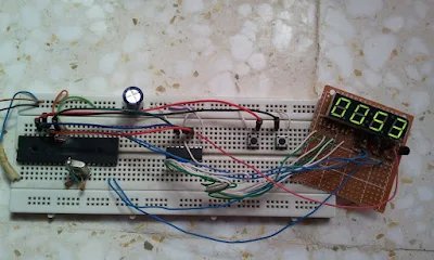
Digital up/down counter using 7 segment display with multiplexing and 74HC595 and PIC16F877A circuit 
There are many topics in this blog talking about the 7-segment display and how to interface it with different types of PIC microcontrollers. One of these topics shows how to interface PIC16F877A with a multiplexed 4-digit 7-segment display with the shift register 74HC164N.
In this topic we are going to see how to make a digital up/down counter using multiplexed 7-segment display with 74HC595 shift register and PIC16F877A microcontroller.
From the 74HC595 datasheet this shift register is a high speed, 8-stage serial shift register with a storage register and 3-state outputs. The registers have separate clocks.
Data is shifted on the positive-going transitions of the shift register clock input (SHCP). The data in each register is transferred to the storage register on a positive-going transition of the storage register clock input (STCP). If both clocks are connected together, the shift register will always be one clock pulse ahead of the storage register.
The following table shows the 74HC595 shift register pin-outs:
74HC595 Shift register pin outs
7-Segment display with 74HC595 shift register:
The following circuit schematic shows a multiplexed 4 digits connected to the 74HC595 shift register. The type of the 7-segment display used in this example is common anode.
In the circuit there are two push buttons, these buttons are used to increment and decrement the displayed number.
7-Segment display with 74HC595 shift register interfacing with PIC16F877A circuit CCS PIC C
7-Segment display with 74HC595 shift register interfacing with PIC16F877A CCS C code:
Here is the example code I think it is a small and clear code.
// 4-Digit 7-Segment display with 74HC595 interfacing with PIC16F877A CCS C code
// http://ccspicc.blogspot.com/
// electronnote@gmail.com

#define data_pin PIN_B0
#define clock_pin PIN_B1
#define latch_pin PIN_B2
#include <16F877A.h>
#fuses HS,NOWDT,NOPROTECT,NOLVP
#use delay(clock = 8000000)
#use fast_io(B)
#use fast_io(D)

short s;                                   // Used to know buttons position
unsigned int j, digit ;
unsigned long i = 0;
unsigned int seg(unsigned int num) {
  switch (num) {
    case 0 : return 0x80;
    case 1 : return 0xF2;
    case 2 : return 0x48;
    case 3 : return 0x60;
    case 4 : return 0x32;
    case 5 : return 0x24;
    case 6 : return 0x04;
    case 7 : return 0xF0;
    case 8 : return 0;
    case 9 : return 0x20;
    }
}
void write_data(unsigned int number){
  for(j = 0x80; j > 0; j = j >> 1) {
     if(number & j)
       output_high(data_pin);
     else
       output_low(data_pin);
     output_high(clock_pin);
     output_low(clock_pin);
   }
     output_high(latch_pin);
     output_low(latch_pin);
}
void main(){
  port_b_pullups(TRUE);                  // Enable PORTB pull-ups
  output_b(0);                           // PORTB initial state
  set_tris_b(0x18);                      // Configure RB3 & RB4 pins as inputs
  output_d(0);                           // PORTD initial state
  set_tris_d(0);                         // Configure PORTD pins as inputs
  while(TRUE){
    if(input(PIN_B3) && input(PIN_B4))
      s = 1;
    if(s == 1) {
      if(input(PIN_B3) == 0) {
       s = 0;
       i++;
       if(i > 9999)
         i = 0;
      }
      if(input(PIN_B4) == 0) {
       s = 0;
       if(i < 1)
         i = 1;
       i--;
      }
    }
    digit = seg(i % 10);                 // Prepare to display ones
    output_d(0x0F);                      // Turn off all displays
    write_data(digit);
    output_d(0x07);                      // Turn on display for ones
    delay_ms(1);
    digit = seg((i / 10) % 10);          // Prepare to display tens
    output_d(0x0F);                      // Turn off all displays
    write_data(digit);
    output_d(0x0B);                      // Turn on display for tens
    delay_ms(1);
    digit = seg((i / 100) % 10);         // Prepare to display hundreds
    output_d(0x0F);                      // Turn off all displays
    write_data(digit);
    output_d(0x0D);                      // Turn on display for hundreds
    delay_ms(1);
    digit = seg((i / 1000) % 10);        // Prepare to display thousands
    output_d(0x0F);                      // Turn off all displays
    write_data(digit);
    output_d(0x0E);                      // Turn on display for thousands
    delay_ms(1);
  }
}

7-Segment display with 74HC595 shift register interfacing with PIC16F877A video:
The following video from a real hardware circuit for the digital counter.

Saturday, August 27, 2016

CCS C UART example for PIC18F4550 microcontroller


This article shows how to get started with PIC18F4550 microcontroller USART module using CCS PIC C compiler.
PIC18F4550 microcontroller has one (1) USART (Universal Synchronous/Asynchronous Receive/Transmit) module. This module can work in USRT mode or UART mode. In this topic we are going to use the USART module as UART (Universal Asynchronous Receive/Transmit) to transmit and receive data between the microcontroller and the computer.
PIC18F4550 UART connection circuit schematic:
Pin RC6 (TX) and pin RC7 (RX) are used for the UART (serial) communication between the microcontroller and the computer. To change between TTL logic levels (5V) and RS232 signals (+/-12V), an IC is needed which is max232.
Don't connect TX and RX pins directly to an RS232 serial port which may damage your microcontroller.
PIC18F4550 microcontroller USART UART example circuit max232 with CCS PIC C
PIC18F4550 UART example CCS C code:
This is the full C code of this example.
// CCS C UART example for PIC18F4550 microcontroller
// http://ccspicc.blogspot.com/
// electronnote@gmail.com

#include <18F4550.h>
#fuses NOMCLR INTRC_IO
#use delay(clock = 8000000)
#use rs232(uart1, baud = 9600)                // Initialize UART module
#include <string.h>

char message[] = "PIC18F4550 microcontroller UART example" ;
char i, j, textsize;
void main(){
  setup_oscillator(OSC_8MHZ);                 // Set internal oscillator to 8MHz
  putc(13);                                   // Go to first column
  printf("Hello world!");                     // UART write
  delay_ms(5000);                             // Wait 5 seconds
  putc(13);                                   // Go to first column
  putc(10);                                   // Start a new line
  textsize = strlen(message);                 // Number of characters in message
  for(j = 0; j < textsize; j++){
    putc(message[j]);
    delay_ms(100);
  }
  putc(13);                                   // Go to first column
  putc(10);                                   // Start a new line
  while(TRUE){
    if(kbhit()){                              // If data has been received
      i = getc();                             // UART read
      putc(i);                                // Send it back
    }
  }
}

PIC18F4550 UART example video:
The following video shows communication between the computer and PIC18F4550 using UART module.

Friday, August 26, 2016

PIC16F877A UART example


PIC16F877A UART example with CCS C
This is a small example shows how to use PIC16F877A UART module using CCS PIC C compiler.
PIC16F877A UART connection circuit schematic:
Pin RC6 (TX) and pin RC7 (RX) are used for the UART (serial) communication between the microcontroller and the computer. To change between TTL logic levels (5V) and RS232 signals (+/-12V), an IC is needed which is max232.
Don't connect TX and RX pins directly to an RS232 serial port which may damage your microcontroller.
CCS C compiler serial monitor can be used to communicate with the microcontroller.
PIC16F877A microcontroller USART UART example circuit max232 with CCS PIC C
PIC16F877A UART example CCS C code:
This is the full C code for this example.
// PIC16F877A UART example with CCS C
// http://ccspicc.blogspot.com/
// electronnote@gmail.com

#include <16F877A.h>
#fuses HS,NOWDT,NOPROTECT,NOLVP
#use delay(clock = 8000000)
#use rs232(uart1, baud = 9600)                // Initialize UART module

char i;
void main(){
  putc(13);                                   // Go to first column
  printf("Hello world!");                     // UART write
  delay_ms(5000);                             // Wait 5 seconds
  putc(13);                                   // Go to first column
  putc(10);                                   // Start a new line
  printf("PIC16F877A UART example");          // UART Write
  putc(13);                                   // Go to first column
  putc(10);                                   // Start a new line
  while(TRUE){
    if(kbhit()){                              // If data has been received
      i = getc();                             // UART read
      putc(i);                                // Send it back
    }
  }
}

PIC16F877A UART example video:

Thursday, August 25, 2016

433MHz RF remote control system based on PIC microcontroller


5-Channel RF (Radio Frequency) remote control transmitter/receiver using PIC18F4550 microcontroller
Today RF modules are widely used in many applications (wireless data transmission, quadcopter, car remote control....).
This project shows how to use low cost 433MHz RF transmitter/receiver modules to build a 5-channel wireless RF remote control system using 2xPIC18F4550 microcontrollers.
The used RF modules in this project are cheap and easy to use with any microcontroller. These modules are shown below with pin configuration:
Radio frequency (RF) transmitter and receiver modules pin configuration.
The following video shows how to get started with low cost RF modules:

Communication protocol:
In this RF project data is transmitted from the transmitter circuit to the receiver circuit using NEC protocol. The NEC protocol uses pulse distance encoding of the bits. Each pulse is a 562.5µs long.
Logic 0: 562.5µs pulse burst followed by a 562.5µs space, with a total transmit time of 1125µs (562.5 x 2).
Logic 1: a 562.5µs pulse burst followed by a 1687.5µs (562.5 x 3) space, with a total transmit time of 2250µs (562.5 x 4).
NEC protocol for RF remote control
The complete extended NEC protocol message is started by 9ms burst followed by 4.5ms space which is then followed by the Address and Command. The address is 16-bit length and the command is transmitted twice (8 bits + 8 bits) where in the second time all bits are inverted and can be used for verification of the received message. The following drawing shows an extended NEC message example.
NEC protocol for RF remote control system
5-Channel RF remote control using PIC18F4550 microcontroller:
This 433MHz RF remote control system has 2 circuits which are transmitter circuit which transmits the RF signals and receiver circuit which receives the RF signals.
RF Transmitter circuit:
The following image shows the RF transmitter circuit schematic diagram where PIC18F4550 microcontroller is used.
In the circuit there are five (5) pushbuttons as shown, each pushbutton sends a different RF signal code via an RF transmitter.
PIC18F4550 internal oscillator is used (8MHz) and MCLR is disabled.
RF Remote control transmitter circuit using PIC18F4550 microcontroller CCS C
RF Transmitter using PIC18F4550 CCS C code:
The following C code is the full code used for the transmitter circuit microcontroller which is written with CCS PIC C compiler PCWHD version 5.0.51.
// 5-Channel RF remote control using PIC18F4550 transmitter CCS C code
// http://ccspicc.blogspot.com/
// electronnote@gmail.com

#include <18F4550.h>
#fuses NOMCLR INTRC_IO
#use delay(clock = 8000000)
#use fast_io(B)
#use fast_io(D)

void send_signal(unsigned int32 number){
  int8 i;
  // Send 9ms pulse
  output_high(PIN_D0);
  delay_ms(9);
  // Send 4.5ms space
  output_low(PIN_D0);
  delay_us(4500);
  // Send data
  for(i = 0; i < 32; i++){
    // If bit is 1 send 560us pulse and 1680us space
    if(bit_test(number, 31 - i)){
      output_high(PIN_D0);
      delay_us(560);
      output_low(PIN_D0);
      delay_us(1680);
    }
    // If bit is 0 send 560us pulse and 560us space
    else{
      output_high(PIN_D0);
      delay_us(560);
      output_low(PIN_D0);
      delay_us(560);
    }
  }
  // Send end bit
  output_high(PIN_D0);
  delay_us(560);
  output_low(PIN_D0);
  delay_us(560);
}
void main(){
  setup_oscillator(OSC_8MHZ);                 // Set internal oscillator to 8MHz
  setup_adc_ports(NO_ANALOGS);                // Configure AN pins as digital
  output_b(0);                                // PORTB initial state
  set_tris_b(0x1F);                           // Configure RB0-to-RB4 as inputs
  port_b_pullups(TRUE);                       // Enable PORTB internal pull-ips
  output_d(0);                                // PORTD initial state
  set_tris_d(0);                              // Configure PORTD pins as outputs
  while(TRUE){
    while(!input(PIN_B0)){
      send_signal(0x40BF00FF);
      delay_ms(500);
    }
    while(!input(PIN_B1)){
      send_signal(0x40BF807F);
      delay_ms(500);
    }
    while(!input(PIN_B2)){
      send_signal(0x40BF40BF);
      delay_ms(500);
    }
    while(!input(PIN_B3)){
      send_signal(0x40BF20DF);
      delay_ms(500);
    }
    while(!input(PIN_B4)){
      send_signal(0x40BFA05F);
      delay_ms(500);
    }
  }
}

RF Receiver circuit:
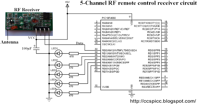
Receiver circuit schematic diagram is shown below.
PIC18F4550 internal oscillator is used (8MHz) and MCLR is disabled.
In the receiver circuit there are 5 LEDs, each LED is controlled by one pushbutton on the transmitter circuit. The RF receiver receives RF signals transmitted from the RF transmitter on the transmitter circuit.
RF Remote control receiver circuit using PIC18F4550 microcontroller CCS C 
RF Receiver using PIC18F4550 CCS C code:
The NEC message has 32 bits which are divided into address (16 bits), command (8 bits) and inverted command (8 bits).
The microcontroller waits until the RF receiver receives an RF signal which makes RB0 goes from logic 0 to logic 1 and the command used is:
while(!input(PIN_B0));
After that a function named remote_read() is called, this function checks if the received signal has NEC protocol form all the time with a resolution of 10us then returns the received code.
// 5-Channel RF remote control using PIC18F4550 receiver CCS C code
// http://ccspicc.blogspot.com/
// electronnote@gmail.com

#include <18F4550.h>
#fuses NOMCLR INTRC_IO
#use delay(clock = 8000000)
#use fast_io(B)

unsigned int32 remote_code;
short remote_read(){
  int8 i;
  unsigned int16 count = 0;
  // Check 9ms pulse (remote control sends logic high)
  while((input(PIN_B0) == 1) && (count < 600)){
    count++;
    delay_us(10);}
  if( (count > 599) || (count < 500))          // NEC protocol?
    return FALSE;                          
  count = 0;
  // Check 4.5ms space (remote control sends logic low)
  while((input(PIN_B0) == 0) && (count < 300)){
    count++;
    delay_us(10);}
  if( (count > 299) || (count < 220))          // NEC protocol?
    return FALSE;                         
  // Read message (32 bits)
  for(i = 0; i < 32; i++){
    count = 0;
    while((input(PIN_B0) == 1) && (count < 45)){
      count++;
      delay_us(10);}
    if( (count > 44) || (count < 25))          // NEC protocol?
      return FALSE;                         
    count = 0;
    while((input(PIN_B0) == 0) && (count < 120)){
      count++;
      delay_us(10);}
    if( (count > 119) || (count < 25))         // NEC protocol?
      return FALSE;
    if( count > 60)                            // If space width > 1ms
      bit_set(remote_code, (31 - i));          // Write 1 to bit (31 - i)
    else                                       // If space width < 1ms
      bit_clear(remote_code, (31 - i));        // Write 0 to bit (31 - i)
  }
  return TRUE;
}
void main(){
  setup_oscillator(OSC_8MHZ);                  // Set internal oscillator to 8MHz
  setup_adc_ports(NO_ANALOGS);                 // Configure AN pins as digital
  output_b(0);                                 // PORTB initial state
  set_tris_b(1);                               // Configure RB0 as digital input pin
  while(TRUE){
    while(!input(PIN_B0));                     // Wait until RB0 pin goes high
    if(remote_read()){
      if(remote_code == 0x40BF00FF)
        output_toggle(PIN_B1);
      if(remote_code == 0x40BF807F)
        output_toggle(PIN_B2);
      if(remote_code == 0x40BF40BF)
        output_toggle(PIN_B3);
      if(remote_code == 0x40BF20DF)
        output_toggle(PIN_B4);
      if(remote_code == 0x40BFA05F)
        output_toggle(PIN_B5);
      }
  }
}

5-Channel RF remote control using PIC18F4550 microcontroller video:
The following video shows a prototype hardware circuit for this project.
In this video I used PORTD instead of PORTB for the 5 outputs of the receiver circuit.


Reference:
http://www.sbprojects.com/