Sunday, September 24, 2017

Distance meter using PIC16F887 and HC-SR04 ultrasonic sensor


This topic shows how to make a simple distance meter using PIC16F887 microcontroller and HC-SR04 ultrasonic sensor.
The HC-SR04 ultrasonic sensor can measure distances form 2cm to 400cm with an accuracy of 3mm. This sensor module includes ultrasonic transmitter, ultrasonic receiver and control circuit.
The HC-SR04 ultrasonic sensor has 4 pins as shown below where:
VCC : Positive power supply (+5V)
Trig : Trigger input pin
Echo : Echo output pin
GND : Ground (0V)
HC-SR04 Ultrasonic sensor pin out
HC-SR04 ultrasonic sensor timing diagram:
The timing diagram of the HC-SR04 ultrasonic sensor is shown below.
First we have to supply the sensor trigger pin with a pulse of 10µs and the sensor will automatically send 8 cycles burst of ultrasound at 40 kHz and raise its echo pin. The Echo is a distance object that is pulse width and the range in proportion. We can calculate the range through the time interval between sending trigger signal and receiving echo signal. Formula: uS / 58 = centimeters or uS / 148 =inch; or:
the range = high level time * sound velocity (340M/S) / 2.
HC-SR04 Ultrasonic sensor timing
Hardware Required:
  • PIC16F887 microcontroller
  • HC-SR04 ultrasonic sensor
  • 16x2 LCD screen
  • 10K variable resistor
  • +5V source
  • Breadboard
  • Jumper Wires
Distance meter using PIC16F887 and HC-SR04 ultrasonic sensor circuit:
Interfacing PIC16F887 with HC-SR04 ultrasonic sensor circuit diagram
In this project the PIC16F887 MCU runs with its internal oscillator and MCLR pin function is disabled.
Distance meter using PIC16F887 and HC-SR04 ultrasonic sensor C code:
The C code below was tested with CCS C compiler version 5.051.
The PIC16F887 runs with its internal oscillator @ 8MHz.
Basically I used Timer1 module to measure the pulse widths which comes from the Echo pin of the HC-SR04 sensor, the width of the pulse is related to the distance. Timer1 is configured to increment every 1us (prescaler = 2):
SETUP_TIMER_1(T1_INTERNAL | T1_DIV_BY_2);
First of all the MCU sends a pulse of 10 us to the sensor via pin RB1 which is the trigger pin of the sensor, then the MCU waits until the sensor raises its Echo pin (function wait_sensor() ). If the waiting time is higher than 990 us ==> time out and the function wait_sensor() returns 0.
if the function wait_sensor() returned 1, the microcontroller starts measuring the width of the Echo pin pulse (in us) using the function get_distance(), if the time > 24990 (distance > 400 cm) ==> out of range, otherwise the measured time will be converted to distance (in cm) by dividing it by 58.
No interrupt is used in this example.
The complete C code is below.
/*
  Distance meter using HC-SR04 ultrasonic sensor and PIC16F887 CCS C code.
  Echo and trigger pins of the HC-SR04 are connected to RB0 and RB1 respectively.
  http://ccspicc.blogspot.com/
  electronnote@gmail.com
*/

//LCD module connections
#define LCD_RS_PIN     PIN_D0
#define LCD_RW_PIN     PIN_D1
#define LCD_ENABLE_PIN PIN_D2
#define LCD_DATA4      PIN_D3
#define LCD_DATA5      PIN_D4
#define LCD_DATA6      PIN_D5
#define LCD_DATA7      PIN_D6
//End LCD module connections

#include <16F887.h>
#fuses INTRC_IO, NOMCLR, NOBROWNOUT, NOLVP
#use delay(clock = 8MHz)
#use fast_io(B)
#include <lcd.c>

int16 i, distance;
int1 wait_sensor(){
  i = 0;
  set_timer1(0);                                 // Reset Timer1
  while(!input(PIN_B0) && (i < 1000))
    i = get_timer1();                            // Read Timer1 and store its value in i
  if(i > 990)
    return 0;
  else
    return 1;
}
int16 get_distance(){
  i = 0;
  set_timer1(0);
  while(input(PIN_B0) && (i < 25000))
    i = get_timer1();
  return i;
}
void main(){
  setup_oscillator(OSC_8MHZ);                    // Set internal oscillator to 8MHz
  output_b(0);
  set_tris_b(1);                                 // Configure RB0 pin as input
  delay_ms(1000);
  lcd_init();                                    // Initialize LCD module
  lcd_putc('\f');                                // Clear LCD
  lcd_gotoxy(4, 1);                              // Go to column 4 row 1
  lcd_putc("Distance:");
  SETUP_TIMER_1(T1_INTERNAL | T1_DIV_BY_2);      // Configure Timer 1 to increment by 1 every 1 us
  while(TRUE){
    // Send 10us pulse to HC-SR04 Trigger pin
    output_high(PIN_B1);
    delay_us(10);
    output_low(PIN_B1);
    // Read pulse comes from HC-SR04 Echo pin
    if(wait_sensor()){
      distance = get_distance();
      if(distance > 24990){
        lcd_gotoxy(3, 2);                        // Go to column 3 row 2
        lcd_putc("Out Of Range");
      }
      else {
        distance = i/58;                         // Calculate the distance
        lcd_gotoxy(3, 2);                        // Go to column 3 row 2
        lcd_putc("       cm   ");
        lcd_gotoxy(6, 2);                        // Go to column 6 row 2
        printf(lcd_putc, "%3Lu", distance);
      }
    }
    else {
      lcd_gotoxy(3, 2);                          // Go to column 3 row 2
      lcd_putc("  Time Out  ");
    }
  delay_ms(100);
  }
}
// End of code
PIC16F887 MCU and HC-SR04 ultrasonic sensor hardware circuit

Tuesday, November 1, 2016

Interfacing PIC12F1822 with HC-SR04 ultrasonic sensor


Distance meter using PIC12F1822 microcontroller and HC-SR04 ultrasonic sensor
This topic shows how to make a simple distance meter using PIC12F1822 microcontroller and HC-SR04 ultrasonic sensor.
I'm not going to write any information about the HC-SR04 ultrasonic sensor because it's well described in its datasheet as well as the following three topics:
PIC16F84A with HC-SR04 ultrasonic sensor example
Interfacing PIC16F877A with HC-SR04 ultrasonic sensor
Interfacing PIC18F4550 Microcontroller with HC-SR04 Ultrasonic Sensor

Components List:
  • PIC12F1822 Microcontroller
  • HC-SR04 Ultrasonic sensor
  • 1602 LCD display
  • 74HC595 Shift Register
  • 10K Variable Resistor
  • +5V Power Source
  • Breadboard
  • Jumper Wires
Interfacing PIC12F1822 with HC-SR04 ultrasonic sensor circuit:
This is our example circuit schematic where internal oscillator of PIC12F1822 is used.
The LCD display is used to display the distance result.
To interface 1602 LCD with PIC12F1822 microcontroller we need 74HC595 shift register as what was done in this post:
Interfacing PIC12F1822 microcontroller with LCD display
Interfacing PIC12F1822 with HC-SR04 ultrasonic sensor CCS C code:
// Interfacing  PIC12F1822 with HC-SR04 ultrasonic sensor CCS PIC C code
// 3-Wire LCD driver must be added
// http://ccspicc.blogspot.com/
// electronnote@gmail.com
// Use at your own risk

//LCD module connections
#define LCD_DATA_PIN PIN_A0
#define LCD_CLOCK_PIN PIN_A1
#define LCD_EN_PIN PIN_A2
//End LCD module connections

#include <12F1822.h>
#fuses NOMCLR INTRC_IO
#use delay(clock = 8000000)
#include <3WireLCD.c>
#use fast_io(A)

unsigned int16 i, distance;
int1 wait_sensor(){
  i = 0;
  set_timer1(0);                                      // Reset Timer1
  while(!input(PIN_A5) && (i < 1000))
    i = get_timer1();                                 // Read Timer1 and store its value in i
  if(i > 990)
    return 0;
  else
    return 1;
}
unsigned int16 get_distance(){
  i = 0;
  set_timer1(0);
  while(input(PIN_A5) && (i < 25000))
    i = get_timer1();
  return i;
}
void main() {
  setup_oscillator(OSC_8MHZ);                         // Set internal oscillator to 8MHz
  setup_adc_ports(NO_ANALOGS);                        // Configure all pins as digital
  set_tris_a(0x20);                                   // Configure RA5 pin as input
  lcd_initialize();                                   // Initialize LCD module
  lcd_cmd(LCD_CLEAR);                                 // LCD Clear
  lcd_goto(4, 1);                                     // Go to column 4 row 1
  lcd_out("Distance:");
  SETUP_TIMER_1(T1_INTERNAL | T1_DIV_BY_2);           // Configure Timer 1 to increment by 1 every 1 us
  while(TRUE){
    // Send 10us pulse to HC-SR04 Trigger pin
    output_high(PIN_A4);
    delay_us(10);
    output_low(PIN_A4);
    // Read pulse comes from HC-SR04 Echo pin
    if(wait_sensor()) {
      distance = get_distance();
      if(distance > 24990) {
        lcd_goto(3, 2);                               // Go to column 3 row 2
        lcd_out("Out Of Range");
      }
      else {
        distance = i/58;                              // Calculate the distance
        lcd_goto(3, 2);                               // Go to column 3 row 2
        lcd_out("       cm   ");
        lcd_goto(6, 2);                               // Go to column 6 row 2
        printf(lcd_out,"%3Lu",distance);
      }
    }
    else {
      lcd_goto(3, 2);                                 // Go to column 3 row 2
      lcd_out("  Time Out  ");
    }
  delay_ms(100);
  }
}

PIC16F84A with HC-SR04 ultrasonic sensor example


Interfacing PIC16F84A with HC-SR04 Ultrasonic Sensor
This post shows how to interface PIC16F84A microcontroller with HC-SR04 ultrasonic sensor and make a distance meter.
The ultrasonic sensor HC-SR04 can measure distances form 2cm to 400cm with an accuracy of 3mm. This sensor module includes ultrasonic transmitter, ultrasonic receiver and control circuit.
The HC-SR04 ultrasonic sensor has 4 pins as shown below where:
VCC - Positive power supply (+5V)
Trig - Trigger input pin
Echo - Echo output pin
GND - Ground (0V)
 HC-SR04 Ultrasonic sensor pinout
HC-SR04 ultrasonic sensor timing diagram:
The timing diagram of the HC-SR04 ultrasonic sensor is shown below.
First we have to supply the sensor trigger pin with a pulse of 10µs and the sensor will automatically send 8 cycles burst of ultrasound at 40 kHz and raise its echo pin. The Echo is a distance object that is pulse width and the range in proportion. You can calculate the range through the time interval between sending trigger signal and receiving echo signal. Formula: uS / 58 = centimeters or uS / 148 =inch; or:
the range = high level time * velocity (340M/S) / 2.
HC-SR04 Ultrasonic sensor timing
PIC16F84A with HC-SR04 ultrasonic sensor example circuit:
The following circuit schematic show he connection between the microcontroller PIC16F84A and the HC-SR04 sensor.
PIC16F84A with HC-SR04 ultrasonic sensor circuit
The 1602 LCD is used to display the measured distance in cm.
PIC16F84A with HC-SR04 ultrasonic sensor example CCS C code:
Here is the C code used for this project.
Timer0 is configured to increment by 1 every 1 us ( with mcu frequency of 8MHz). Timer0 is used the measure the pulse widths come from Echo pin of the HC-SR04 sensor.
Because of the Timer0 is an 8-bit timer only I used its interrupt (Timer0 interrupt) to count times more than 256us, and for that purpose I added a variable called count. So the pulse time of the Echo pin equals to :
count * 256 + get_timer0()
// Interfacing  PIC16F84A with HC-SR04 ultrasonic sensor CCS PIC C code
// http://ccspicc.blogspot.com/
// electronnote@gmail.com

//LCD module connections
#define LCD_RS_PIN PIN_B0
#define LCD_RW_PIN PIN_B1
#define LCD_ENABLE_PIN PIN_B2
#define LCD_DATA4 PIN_B3
#define LCD_DATA5 PIN_B4
#define LCD_DATA6 PIN_B5
#define LCD_DATA7 PIN_B6
//End LCD module connections

#include <16F84A.h>
#fuses HS,NOWDT,PUT,NOPROTECT
#use delay(clock = 8000000)
#include <lcd.c>
#use fast_io(A)

unsigned int8 count;
unsigned int16 i, distance;
#INT_TIMER0
void timer0_isr(){
  count++;
  clear_interrupt(INT_TIMER0);
}
int1 wait_sensor(){
  i = 0;
  set_timer0(0);
  count = 0;                             // Reset Timer0
  while(!input(PIN_A1) && (i < 1000))
    i = count * 256 + get_timer0();
  if(i > 990)
    return 0;
  else
    return 1;
}
unsigned int16 get_distance(){
  i = 0;
  set_timer0(0);
  count = 0;
  while(input(PIN_A1) && (i < 25000))
    i = count * 256 + get_timer0();
  return i;
}
void main(){
  output_a(0);
  set_tris_a(2);                                      // Configure RA1 as input
  lcd_init();                                         // Initialize LCD module
  lcd_putc('\f');                                     // LCD clear
  clear_interrupt(INT_TIMER0);
  enable_interrupts(GLOBAL);
  enable_interrupts(INT_TIMER0);
  setup_timer_0 (T0_INTERNAL | T0_DIV_2);             // Configure Timer0 module
  lcd_gotoxy(4, 1);                                   // Go to column 4 row 1
  lcd_putc("Distance:");
  while(TRUE){
    // Send 10us pulse to HC-SR04 Trigger pin
    output_high(PIN_A0);
    delay_us(10);
    output_low(PIN_A0);
    // Read pulse comes from HC-SR04 Echo pin
    if(wait_sensor()) {
      distance = get_distance();
      if(distance > 24990) {
        lcd_gotoxy(3, 2);                             // Go to column 3 row 2
        lcd_putc("Out Of Range");
      }
      else {
        distance = i/58;                              // Calculate the distance
        lcd_gotoxy(3, 2);                             // Go to column 3 row 2
        lcd_putc("       cm   ");
        lcd_gotoxy(6, 2);                             // Go to column 6 row 2
        printf(lcd_putc,"%3Lu",distance);
      }
    }
    else {
      lcd_gotoxy(3, 2);                               // Go to column 3 row 2
      lcd_putc("  Time Out  ");
    }
  delay_ms(100);
  }
}
Example Video:

Thursday, September 1, 2016

Interfacing PIC18F4550 Microcontroller with HC-SR04 Ultrasonic Sensor


Distance measurement using PIC18F4550 microcontroller and HC-SR04 ultrasonic sensor
The distance to an obstacle can be measured with the low cost ultrasonic sensor HC-SR04 (HC-SR05). The HC-SR04 sensor can measure distances form 2 to 400cm with an accuracy of 3mm. This sensor module includes ultrasonic transmitter, ultrasonic receiver and control circuit.
The HC-SR04 ultrasonic sensor has 4 pins as shown below where:
VCC - Positive power supply (+5V)
Trig - Trigger input pin
Echo - Echo output pin
GND - Ground (0V)
HC-SR04 Ultrasonic sensor for distance measurement 
HC-SR04 ultrasonic sensor timing diagram:
The timing diagram of the HC-SR04 ultrasonic sensor is shown below.
First we have to supply the sensor trigger pin with a pulse of 10µs and the sensor will automatically send 8 cycles burst of ultrasound at 40 kHz and raise its echo pin. The Echo is a distance object that is pulse width and the range in proportion. You can calculate the range through the time interval between sending trigger signal and receiving echo signal. Formula: uS / 58 = centimeters or uS / 148 =inch; or:
the range = high level time * velocity (340M/S) / 2.
HC-SR04 Ultrasonic sensor for distance measurement timing
Interfacing PIC18F4550 with HC-SR04 ultrasonic sensor circuit:
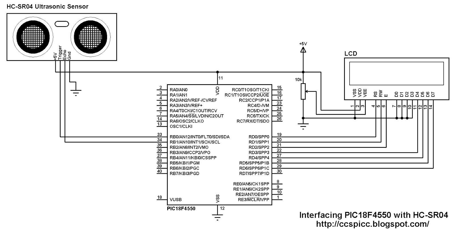
Project circuit schematic is shown below.
Interfacing PIC18F4550 with HC-SR04 ultrasonic sensor circuit
The microcontroller runs with its internal oscillator at 8MHz.
HC-SR04 Ultrasonic sensor Trigger pin is connected to RB0 pin and  the Echo pin is connected to RB1 pin.
Interfacing PIC18F4550 with HC-SR04 ultrasonic sensor CCS C code:
Here are some hints about the C code.
The sensor needs at least 10µs pulse at Trigger pin which is done as follows (Trigger pin is connected to RB0 pin:
output_high(PIN_B0);
delay_us(10);
output_low(PIN_B0);

After sending the trigger pulse we have to wait until the module raises its Echo output pin where the Echo pin is connected to pin RB1. If the waiting time is too long that means there is a problem and the code returns error. Timer1 module is used to count elapsed time which is configured to increment by 1 every 1µs (8MHz mcu frequency used).
If you choose to run your microcontroller with different frequency you have to change Timer1 configuration, otherwise you will get a wrong results.
setup_timer_1 (T1_INTERNAL | T1_DIV_BY_2);
Waiting HC-SR04 module to raise its Echo pin with timeout property code where variable check is used as a return variable (if there is a timeout problem check = 1).
The timeout property is used to prevent the microcontroller from hanging.
while(!input(PIN_B1) && (get_timer1() < 1000));
if(get_timer1() > 990)
  check = 1;

If there is no problem the module raises its Echo pin for a certain time, this time is proportional to distance from the sensor the the obstacle. Timer1 is used to count this time as follows:
while(input(PIN_B1) && (i < 25000))
  i = get_timer1();
if(i > 24990)
  check = 2;

If there is an out of range the code returns error by making the variable check = 2.
For the variable check:
If check = 0: There is no problem
If check = 1: There is a timeout error
If check = 2: There is an out of range error.
Project full code is as below:
// Interfacing PIC18F4550 with HC-SR04 usltrasonic sensor CCS C code
// http://ccspicc.blogspot.com/
// electronnote@gmail.com


//LCD module connections
#define LCD_RS_PIN PIN_D0
#define LCD_RW_PIN PIN_D1
#define LCD_ENABLE_PIN PIN_D2
#define LCD_DATA4 PIN_D3
#define LCD_DATA5 PIN_D4
#define LCD_DATA6 PIN_D5
#define LCD_DATA7 PIN_D6
//End LCD module connections

#include <18F4550.h>
#fuses NOMCLR INTRC_IO
#use delay(clock = 8000000)
#include <lcd.c>
#use fast_io(B)

int8 check;
unsigned int16 i, distance;
void main(){
  setup_oscillator(OSC_8MHZ);                      // Set internal oscillator to 8MHz
  setup_adc_ports(NO_ANALOGS);
  output_b(0);
  set_tris_b(2);                                   // Configure RB1 as input
  lcd_init();                                      // Initialize LCD module
  setup_timer_1 (T1_INTERNAL | T1_DIV_BY_2);       // Configure Timer1 module
  set_timer1(0);                                   // Reset Timer1
  lcd_putc('\f');                                  // LCD Clear
  lcd_gotoxy(4, 1);                                // Go to column 4 row 1
  lcd_putc("Distance:");
  while(TRUE){
    check = 0;
    i = 0;
    output_high(PIN_B0);
    delay_us(10);
    output_low(PIN_B0);
    set_timer1(0);                                 // Reset Timer1
    while(!input(PIN_B1) && (get_timer1() < 1000));
    if(get_timer1() > 990)
      check = 1;                                   // Timeout error
    set_timer1(0);                                 // Reset Timer1
    while(input(PIN_B1) && (i < 25000))
      i = get_timer1();                            // Store Timer1 value in i 
    if(i > 24990)                                  // Out of range error
      check = 2;
    if(check == 1){
      lcd_gotoxy(3, 2);                            // Go to column 3 row 2
      lcd_putc("  Time Out  ");
    }
    if(check == 2){
      lcd_gotoxy(3, 2);                            // Go to column 3 row 2
      lcd_putc("Out Of Range");
    }
    else{
      distance = i/58;                             // Calculate the distance
      lcd_gotoxy(3, 2);                            // Go to column 3 row 2
      lcd_putc("       cm   ");
      lcd_gotoxy(6, 2);                            // Go to column 6 row 2
      printf(lcd_putc,"%3Lu",distance);
    }
    delay_ms(100);
  }
}

Interfacing PIC18F4550 with HC-SR04 ultrasonic sensor video:
The following video shows the project in prototype hardware circuit.

Interfacing PIC16F877A with HC-SR04 ultrasonic sensor


Distance measurement using PIC16F877A microcontroller and HC-SR04 ultrasonic sensor
HC-SR04 and PIC16F877A in prototype circuit 
The distance to an obstacle can be measured with the low cost ultrasonic sensor HC-SR04 (HC-SR05). The HC-SR04 sensor can measure distances form 2 to 400cm with an accuracy of 3mm. This sensor module includes ultrasonic transmitter, ultrasonic receiver and control circuit.
The HC-SR04 ultrasonic sensor has 4 pins as shown below where:
VCC - Positive power supply (+5V)
Trig - Trigger input pin
Echo - Echo output pin
GND - Ground (0V)
HC-SR04 Ultrasonic sensor pin outs
HC-SR04 ultrasonic sensor timing diagram:
The timing diagram of the HC-SR04 ultrasonic sensor is shown below.
First we have to supply the sensor trigger pin with a pulse of 10µs and the sensor will automatically send 8 cycles burst of ultrasound at 40 kHz and raise its echo pin. The Echo is a distance object that is pulse width and the range in proportion. You can calculate the range through the time interval between sending trigger signal and receiving echo signal. Formula: uS / 58 = centimeters or uS / 148 =inch; or:
the range = high level time * velocity (340M/S) / 2.
HC-SR04 Ultrasonic sensor  timing
Interfacing PIC16F877A with HC-SR04 ultrasonic sensor circuit:
Project circuit schematic is shown below.
Interfacing PIC16F877A with HC-SR04 ultrasonic sensor circuit
The microcontroller runs with 8MHz crystal oscillator.
HC-SR04 Ultrasonic sensor Trigger pin is connected to RB0 pin and  the Echo pin is connected to RB1 pin.
Interfacing PIC16F877A with HC-SR04 ultrasonic sensor CCS C code:
Here are some hints about the C code.
The sensor needs at least 10µs pulse at Trigger pin which is done as follows (Trigger pin is connected to RB0 pin:
output_high(PIN_B0);
delay_us(10);
output_low(PIN_B0);

After sending the trigger pulse we have to wait until the module raises its Echo output pin where the Echo pin is connected to pin RB1. If the waiting time is too long that means there is a problem and the code returns error. Timer1 module is used to count elapsed time which is configured to increment by 1 every 1µs (8MHz mcu frequency used).
setup_timer_1 (T1_INTERNAL | T1_DIV_BY_2);
Waiting HC-SR04 module to raise its Echo pin with timeout property code where variable check is used as a return variable (if there is a timeout problem check = 1).
The timeout property is used to prevent the microcontroller from hanging.
while(!input(PIN_B1) && (get_timer1() < 1000));
if(get_timer1() > 990)
  check = 1;

If there is no problem the module raises its Echo pin for a certain time, this time is proportional to distance from the sensor the the obstacle. Timer1 is used to count this time as follows:
while(input(PIN_B1) && (i < 25000))
  i = get_timer1();
if(i > 24990)
  check = 2;

If there is an out of range the code returns error by making the variable check = 2.
For the variable check:
If check = 0: There is no problem
If check = 1: There is a timeout error
If check = 2: There is an out of range error.
Project full code is as below:
// Interfacing PIC16F877A with HC-SR04 ultrasonic sensor CCS C code
// http://ccspicc.blogspot.com/
// electronnote@gmail.com

//LCD module connections
#define LCD_RS_PIN PIN_D0
#define LCD_RW_PIN PIN_D1
#define LCD_ENABLE_PIN PIN_D2
#define LCD_DATA4 PIN_D3
#define LCD_DATA5 PIN_D4
#define LCD_DATA6 PIN_D5
#define LCD_DATA7 PIN_D6
//End LCD module connections

#include <16F877A.h>
#fuses HS,NOWDT,NOPROTECT,NOLVP
#use delay(clock = 8000000)
#include <lcd.c>
#use fast_io(B)

int8 check;
unsigned int16 i, distance;
void main(){
  output_b(0);
  set_tris_b(2);                                   // Configure RB1 as input
  lcd_init();                                      // Initialize LCD module
  setup_timer_1 (T1_INTERNAL | T1_DIV_BY_2);       // Configure Timer1 module
  set_timer1(0);                                   // Reset Timer1
  lcd_putc('\f');                                  // LCD Clear
  lcd_gotoxy(4, 1);                                // Go to column 4 row 1
  lcd_putc("Distance:");
  while(TRUE){
    check = 0;
    i = 0;
    output_high(PIN_B0);
    delay_us(10);
    output_low(PIN_B0);
    set_timer1(0);                                 // Reset Timer1
    while(!input(PIN_B1) && (get_timer1() < 1000));
    if(get_timer1() > 990)
      check = 1;                                   // Timeout error
    set_timer1(0);                                 // Reset Timer1
    while(input(PIN_B1) && (i < 25000))
      i = get_timer1();                            // Store Timer1 value in i 
    if(i > 24990)                                  // Out of range error
      check = 2;
    if(check == 1){
      lcd_gotoxy(3, 2);                            // Go to column 3 row 2
      lcd_putc("  Time Out  ");
    }
    if(check == 2){
      lcd_gotoxy(3, 2);                            // Go to column 3 row 2
      lcd_putc("Out Of Range");
    }
    else{
      distance = i/58;                             // Calculate the distance
      lcd_gotoxy(3, 2);                            // Go to column 3 row 2
      lcd_putc("       cm   ");
      lcd_gotoxy(6, 2);                            // Go to column 6 row 2
      printf(lcd_putc,"%3Lu",distance);
    }
    delay_ms(100);
  }
}

Interfacing PIC16F877A with HC-SR04 ultrasonic sensor video:
The following video shows project prototype circuit.