Friday, September 8, 2017

Interfacing PIC12F1822 with 1602 LCD and LM35 temperature sensor


This post shows a simple interfacing of PIC16F1822 microcontroller with 16x2 LCD and LM35 analog temperature sensor.
The LM35 temperature sensor is a three pin device (VCC, OUT and GND) with an output voltage linearly related to Centigrade temperature. Since the LM35 output varies with dependent to the temperature we need ADC (Analog-to-Digital Converter) module to measure this voltage.
The LM35 output has linear +10mV/°C scale factor means the following:
If the output voltage =   10mV ---> temperature =   1°C
If the output voltage = 100mV ---> temperature = 10°C
If the output voltage = 200mV ---> temperature = 20°C
If the output voltage = 370mV ---> temperature = 37°C
and so on.
LM35 Futures (from datasheet):
  • Calibrated Directly in ° Celsius (Centigrade)
  • Linear + 10 mV/°C Scale Factor
  • 0.5°C Ensured Accuracy (at +25°C)
  • Rated for Full −55°C to +150°C Range
  • Suitable for Remote Applications
  • Low Cost Due to Wafer-Level Trimming
  • Operates from 4 to 30 V
  • Less than 60-μA Current Drain
  • Low Self-Heating, 0.08°C in Still Air
  • Nonlinearity Only ±¼°C Typical
  • Low Impedance Output, 0.1 Ω for 1 mA Load
The ADC module converts analog data into digital data. The PIC12F1822 MCU has a 10-bit ADC module and a built-in fixed voltage reference (FVR) which makes it a good choice for this application. With the fixed voltage reference we get approximately an exact result. Normally negative and positive references of the ADC module are VSS and VDD respectively, but VDD is not exactly equal to 5.00V and here we should use the fixed voltage reference as a positive reference of the ADC module.
The PIC12F1822 has 3 fixed voltage references: 1.024V, 2.048V and 4.096V. For example if we set the fixed voltage reference to 4.096V and the ADC module is configured so that the negative and the positive references are VSS and FVR (Fixed Voltage Reference) respectively, in this case the equivalent 10-bit digital value of 4.096 is 1023 and 3.00V is 3.00 * 1023/4.096 = 749 , and so on.
In this project I used FVR = 1.024V because the LM35 output is generally less than 1V and also it gave me better result (let's say higher resolution). Now the ADC module works in the interval between 0 and 1.024V.
The temperature value is displayed on 1602 LCD display. This LCD is interfaced with the microcontroller using 74HC595 (74HC164 .....) shift register as what was done in this post:
Interfacing PIC12F1822 microcontroller with LCD display
Hardware Required:
  • PIC12F1822 microcontroller
  • LM35 temperature sensor  -- datasheet
  • 1602 LCD screen
  • 74HC595 shift register
  • 10K ohm variable resistor
  • Breadboard
  • 5V voltage source
  • Jumper wires
Interfacing PIC12F1822 with LM35 sensor circuit:
Interfacing PIC12F1822 microcontroller with LM35 sensor circuit
The output of the LM35 temperature sensor is connected to analog channel 0 (RA0) of the PIC12F1822 microcontroller.
The 1602 LCD display pins are connected to 74HC595 shift register except the Enable pin (E) which is connected directly to the PIC12F1822 MCU. With the help of the shift register 74HC595, the LCD uses only 3 data lines: clock, data and enable. Other types of serial-in parallel-out shift registers can be used such as 74HC164 and CD4094 (74HC4094).
In this example the PIC12F1822 MCU uses its internal oscillator and MCLR pin function is disabled.
Interfacing PIC12F1822 with LM35 temperature sensor C code:
The C code below was tested with CCS PIC C compiler version 5.051.
Reading voltage quantity using the ADC gives us a number between 0 and 1023 (10-bit resolution), 0V is represented by 0 and 1.024V is represented by 1023 (ADC positive reference comes from FVR which is set to 1.024V) . Converting back the ADC digital value is easy, we can use the following equation for that conversion:
Voltage (in Volts) = ADC reading * 1.024 / 1024
Multiplying the previous result by 100 (LM35 scale factor is 10mV/°C = 0.01V/°C) will gives the actual temperature:
Temperature(°C) = ADC reading * 0.1
where 0.1 = 100 * 1.024 / 1024
The complete C code is the one below.
/* Interfacing PIC12F1822 with LM35 temperature sensor C code.
   The temperature result is displayed on 1602 LCD screen with
   the help of a shift register (74HC595, 74HC164 ....).
   Serial LCD driver for CCS C must be added to the project.
   http://ccspicc.blogspot.com/
   electronnote@gmail.com
*/

// Serial LCD module connections
#define LCD_DATA_PIN  PIN_A5
#define LCD_CLOCK_PIN PIN_A4
#define LCD_EN_PIN    PIN_A2
// End serial LCD module connections

#include <12F1822.h>
#device ADC = 10
#fuses NOMCLR INTRC_IO PLL_SW
#use delay(clock=32000000)
#use fast_io(A)
#include <3WireLCD.c>                            // 3-wire serial LCD driver source file

float temp;
void main() {
  setup_oscillator(OSC_8MHZ | OSC_PLL_ON);       // Set internal oscillator to 8MHz with PLL enabled (32MHz)
  lcd_initialize();                              // Initialize LCD module
  lcd_cmd(LCD_CLEAR);                            // LCD Clear
  setup_vref(VREF_ADC_1v024);                    // Configure FVR to supply ADC positive reference with 1.024V
  setup_adc(ADC_CLOCK_INTERNAL);                 // ADC Module uses its internal oscillator
  setup_adc_ports(sAN0 | VSS_FVR);               // Configure AN0 pin as analog - Voltage reference: VSS - FVR(1.024V)
  set_adc_channel(0);                            // Select channel 0 (AN0)
  lcd_goto(3, 1);                                // Go to column 3 row 1
  printf(lcd_out, "Temperature:");
 while(TRUE){
    delay_ms(1000);
    temp = read_adc() * 0.1;                     // Read analog voltage and convert it to Kelvin (0.1 = 100*1.024/1024)
    lcd_goto(6, 2);                              // Go to column 6 row 2
    printf(lcd_out, "%4.1fßC", temp);            // Display LM35 temperature result (float format)
  }
}
The Result:
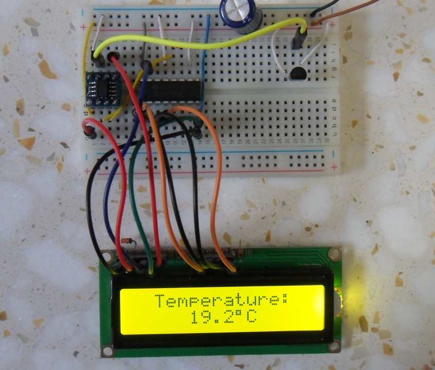
PIC12F1822 with LM35 temperature sensor hardware circuit

Thursday, September 7, 2017

PIC12F1822 + 1602 LCD + LM335 Temperature Sensor


the LM335 is a 3-pin analog device which can measure temperature (converts temperature to analog voltage). This sensor requires an ADC to convert the analog data into digital data.
This topic shows how to build a thermometer using PIC12F1822 microcontroller and LM335 analog temperature sensor.
The LM335 sensor has the following features (from LM335 datasheet):
  • Directly Calibrated to the Kelvin Temperature Scale
  • 1°C Initial Accuracy Available
  • Operates from 400 μA to 5 mA
  • Less than 1-Ω Dynamic Impedance
  • Easily Calibrated
  • Wide Operating Temperature Range
  • 200°C Overrange
  • Low Cost
The LM135 has a breakdown voltage directly proportional to absolute temperature at 10 mV/°K. For example if the LM335 output voltage is equal to 3.03 (3030 mV) that means the temperature is: 303 Kelvin = 30 °Celsius.
The PIC12F1822 is an 8-bit microcontroller which has 4 analog channels with 10-bit resolution. The good thing with this microcontroller is the fixed voltage reference. With the fixed voltage reference we get approximately an exact result. Normally negative and positive references of the ADC module are VSS and VDD, but VDD is not exactly equal to 5.00V and here we should use the fixed voltage reference as a positive reference of the ADC module.
The PIC12F1822 has 3 fixed voltage references: 1.024V, 2.048V and 4.096V. For example if we set the fixed voltage reference to 4.096V and the ADC module is configured so that the negative and the positive references are VSS and FVR (Fixed Voltage Reference) respectively, in this case the equivalent 10-bit digital value of 4.096 is 1023 and 3.00V is 3.00 * 1023/4.096 = 749 , and so on.
In this project I used 4.096 because the LM335 output is between 2.23V (temperature = -50°C) and 3.98V (temperature = +125°C).
The temperature values (Kelvin and degree Celsius) are displayed on 1602 LCD display. This LCD is interfaced with the microcontroller using 74HC595 (74HC164 .....) shift register as what was done in this post:
Interfacing PIC12F1822 microcontroller with LCD display
Hardware Required:
  • PIC12F1822 microcontroller
  • LM335 Temperature sensor - datasheet
  • 1602 LCD Screen
  • 74HC595 shift register
  • 10K ohm variable resistor
  • 2.2K ohm resistor
  • +5V Power supply source
  • Breadboard
  • Jumper wires
Interfacing PIC12F1822 with LM335 temperature sensor circuit:
Interfacing PIC12F1822 MCU with LM335 temperature sensor and 1602 LCD circuit
The LM335 sensor has 3 pins (from left to right):
Pin 1 for calibration, not used in this example
Pin 2: output
Pin 3: GND (ground).
The output pin of the LM335 sensor is connected to analog channel 0 (RA0). I chose the 2.2K ohm because as written in the datasheet for optimum accuracy the current flows through the LM335 should be 1mA. For example if the temperature = 27°C, the output will be 3.00V and assume the supply voltage is exactly 5.00V that means the current flows through the sensor is ( 5 - 3)/2.2 = 0.90mA which is good enough. Also the value 2.2K is a standard value and well used.
The 1602 LCD display pins are connected to 74HC595 shift register except the Enable pin (E) which is connected directly to PIC12F1822. With the help of the shift register 74HC595 the LCD uses only 3 data lines: clock, data and enable. Other types of serial-in parallel-out shift registers can be used such as 74HC164 and CD4094 (74HC4094).
In this example the PIC12F1822 MCU uses its internal oscillator and MCLR pin function is disabled.
Interfacing PIC12F1822 with LM335 temperature sensor C code:
This code was tested with CCS PIC C compiler version 5.051.
To compile the C code below, the serial LCD driver source file must be added to the project just by downloading the source file and putting it on the project folder. The download link of the serial LCD driver is in this post:
3-Wire LCD driver for CCS PIC C compiler
The complete C code is the one below.
/* Thermometer using PIC12F1822 microcontroller and LM335 sensor C code.
   The temperature results (kelvin and degree Celsius) are displayed on
   1602 LCD screen with the help of a shift register (74HC595, 74HC164 ....).
   Serial LCD driver for CCS C must be added to the project.
   http://ccspicc.blogspot.com/
   electronnote@gmail.com
*/

// Serial LCD module connections
#define LCD_DATA_PIN  PIN_A5
#define LCD_CLOCK_PIN PIN_A4
#define LCD_EN_PIN    PIN_A2
// End serial LCD module connections

#include <12F1822.h>
#device ADC = 10
#fuses NOMCLR INTRC_IO PLL_SW
#use delay(clock=32000000)
#use fast_io(A)
#include <3WireLCD.c>                            // 3-wire serial LCD driver source file

char celsius_temp[] = "Temp =  00.0ßC";
char kelvin_temp[]  =      "=  00.0 K";
signed int16 Kelvin, Celsius;
void main() {
  setup_oscillator(OSC_8MHZ | OSC_PLL_ON);       // Set internal oscillator to 8MHz with PLL enabled (32MHz)
  lcd_initialize();                              // Initialize LCD module
  lcd_cmd(LCD_CLEAR);                            // LCD Clear
  setup_vref(VREF_ADC_4v096);                    // Configure FVR to supply ADC positive reference with 4.096V
  setup_adc(ADC_CLOCK_INTERNAL);                 // ADC Module uses its internal oscillator
  setup_adc_ports(sAN0 | VSS_FVR);               // Configure AN0 pin as analog - Voltage reference: VSS - FVR(4.096V)
  set_adc_channel(0);                            // Select channel 0 (AN0)
 while(TRUE){
    delay_ms(1000);
    Kelvin = (read_adc() + 1) * 0.4;             // Read analog voltage and convert it to Kelvin (0.4 = 100*4.096/1024)
    Celsius = Kelvin - 273;                      // Convert Kelvin to degree Celsius
    if(Celsius < 0){
      Celsius = abs(Celsius);                    // Absolute value
      celsius_temp[7] = '-';                     // Put minus '-' sign
    }
    else
      celsius_temp[7]  = ' ';                    // Put space ' '
    if (Celsius > 99)
      celsius_temp[7]  = '1';                    // Put 1 (of hundred)
    celsius_temp[8]  = (Celsius / 10) % 10  + 48;
    celsius_temp[9]  =  Celsius % 10  + 48;
    kelvin_temp[2]   = (Kelvin / 100) % 10 + 48;
    kelvin_temp[3]   = (Kelvin / 10) % 10 + 48;
    kelvin_temp[4]   =  Kelvin % 10 + 48;
    lcd_goto(1, 1);                              // Go to column 1 row 1
    printf(lcd_out, celsius_temp);               // Display Celsius_temp
    lcd_goto(6, 2);                              // Go to column 6 row 2
    printf(lcd_out, kelvin_temp);                // Display kelvin_temp
  }
}
The Result:
A hardware circuit of PIC12F1822 MCU, LCD and LM335 temperature sensor

Tuesday, November 1, 2016

Interfacing PIC12F1822 with HC-SR04 ultrasonic sensor


Distance meter using PIC12F1822 microcontroller and HC-SR04 ultrasonic sensor
This topic shows how to make a simple distance meter using PIC12F1822 microcontroller and HC-SR04 ultrasonic sensor.
I'm not going to write any information about the HC-SR04 ultrasonic sensor because it's well described in its datasheet as well as the following three topics:
PIC16F84A with HC-SR04 ultrasonic sensor example
Interfacing PIC16F877A with HC-SR04 ultrasonic sensor
Interfacing PIC18F4550 Microcontroller with HC-SR04 Ultrasonic Sensor

Components List:
  • PIC12F1822 Microcontroller
  • HC-SR04 Ultrasonic sensor
  • 1602 LCD display
  • 74HC595 Shift Register
  • 10K Variable Resistor
  • +5V Power Source
  • Breadboard
  • Jumper Wires
Interfacing PIC12F1822 with HC-SR04 ultrasonic sensor circuit:
This is our example circuit schematic where internal oscillator of PIC12F1822 is used.
The LCD display is used to display the distance result.
To interface 1602 LCD with PIC12F1822 microcontroller we need 74HC595 shift register as what was done in this post:
Interfacing PIC12F1822 microcontroller with LCD display
Interfacing PIC12F1822 with HC-SR04 ultrasonic sensor CCS C code:
// Interfacing  PIC12F1822 with HC-SR04 ultrasonic sensor CCS PIC C code
// 3-Wire LCD driver must be added
// http://ccspicc.blogspot.com/
// electronnote@gmail.com
// Use at your own risk

//LCD module connections
#define LCD_DATA_PIN PIN_A0
#define LCD_CLOCK_PIN PIN_A1
#define LCD_EN_PIN PIN_A2
//End LCD module connections

#include <12F1822.h>
#fuses NOMCLR INTRC_IO
#use delay(clock = 8000000)
#include <3WireLCD.c>
#use fast_io(A)

unsigned int16 i, distance;
int1 wait_sensor(){
  i = 0;
  set_timer1(0);                                      // Reset Timer1
  while(!input(PIN_A5) && (i < 1000))
    i = get_timer1();                                 // Read Timer1 and store its value in i
  if(i > 990)
    return 0;
  else
    return 1;
}
unsigned int16 get_distance(){
  i = 0;
  set_timer1(0);
  while(input(PIN_A5) && (i < 25000))
    i = get_timer1();
  return i;
}
void main() {
  setup_oscillator(OSC_8MHZ);                         // Set internal oscillator to 8MHz
  setup_adc_ports(NO_ANALOGS);                        // Configure all pins as digital
  set_tris_a(0x20);                                   // Configure RA5 pin as input
  lcd_initialize();                                   // Initialize LCD module
  lcd_cmd(LCD_CLEAR);                                 // LCD Clear
  lcd_goto(4, 1);                                     // Go to column 4 row 1
  lcd_out("Distance:");
  SETUP_TIMER_1(T1_INTERNAL | T1_DIV_BY_2);           // Configure Timer 1 to increment by 1 every 1 us
  while(TRUE){
    // Send 10us pulse to HC-SR04 Trigger pin
    output_high(PIN_A4);
    delay_us(10);
    output_low(PIN_A4);
    // Read pulse comes from HC-SR04 Echo pin
    if(wait_sensor()) {
      distance = get_distance();
      if(distance > 24990) {
        lcd_goto(3, 2);                               // Go to column 3 row 2
        lcd_out("Out Of Range");
      }
      else {
        distance = i/58;                              // Calculate the distance
        lcd_goto(3, 2);                               // Go to column 3 row 2
        lcd_out("       cm   ");
        lcd_goto(6, 2);                               // Go to column 6 row 2
        printf(lcd_out,"%3Lu",distance);
      }
    }
    else {
      lcd_goto(3, 2);                                 // Go to column 3 row 2
      lcd_out("  Time Out  ");
    }
  delay_ms(100);
  }
}

Monday, October 24, 2016

RC5 IR Remote Control Decoder with PIC12F1822 Microcontroller


This topic shows an easy and effective way for decoding IR (Infra-Red) remote controls that use Philips RC-5 communication protocol, but first we've to understand how the RC5 protocol works.
This Wikipedia links has good infos about the RC5 protocol.
The RC-5 protocol was developed by Philips in the late 1980s as a semi-proprietary consumer IR (infrared) remote control communication protocol for consumer electronics.
The RC5 has 14 bits per 1 code transmission, the 14 bits can be divided into 4 parts:
The first 2 bits are start bits and they are always logic 1.
The third bit called toggle bit, it can be logic 1 or logic 0.
The next 5 bits are address bits, each device type has its address number for example TV address number is 0, CD player address = 20 ............
And the last 6 bits are command bits, each button has its command number.
For the same device for example TV all the remote control buttons has the same address but each button has its command.
The toggle bit changes whenever a button is pressed.
The RC5 protocol uses Manchester coding, logic 1 and logic 0 are coded as shown in the following drawing where toggle bit is 1, address = 0 and command is 2:
RC-5 protocol message code 14 bits 
RC5 Protocol state machine:
I used the state machine shown below for decoding the RC5 protocol. The RC5 state machine checks the length of pulses and spaces transmitted from the remote control to go from state to another.
RC5 protocol state machine for PIC microcontroller
Where:
SP : Short Pulse (About 889µs)
LP : Long Pulse (About 1778µs)
SS: Short Space (About 889µs)
LS : Long Space (About 1778µs)
Basically there are 4 states: Mid1, Mid0, Start1 and Start0.
RC5 IR Remote Control Decoder with PIC12F1822 Microcontroller Circuit:
RC5 IR Remote Control Decoder with PIC12F1822 microcontroller circuit
Components List:
  • PIC12F1822 Microcontroller
  •  1602 LCD
  • 74HC595 Shift Register (74HC164, CD4094 ....)
  • IR Receiver
  • 47µF Capacitor
  • 10K Resistor
  • 10K Variable Resistor
  • +5V Power Supply
  • Protoboard
  • Jumper Wires
To interface 1602 LCD with PIC12F1822 microcontroller we need 74HC595 shift register as what was done in this post:
Interfacing PIC12F1822 microcontroller with LCD display
The IR receiver is used to receive the IR signals transmitted from the remote control and convert this signals to a digital data (logic 0 and logic 1). The microcontroller reads digital data from the IR receiver, this data is decoded and the results displayed on the 1602 LCD.
The idle state of the IR receiver output is logic 1 (+5V). When the IR receiver receives a pulse which comes from the remote control its output (IR receiver) gives logic 0 (0V).
PIC12F1822 internal oscillator is used and MCLR pin is configured as digital input.
RC5 IR Remote Control Decoder with PIC12F1822 CCS C Code:
Timer1 is configured to increment by 1 every 1µs, it is used to measure pulses and spaces widths.
To measure pulses and spaces width in µs I used two functions and I called them respectively:
test_pulse() and test_space().
The previous two functions returns the following three values:
0 : If the width is out of range
1 : If the width is long (long pulse or long space)
2 : If the width is short (short pulse or short space)
If the IR receives an IR signal its output pin goes from logic 1 to logic 0 which causes the microcontroller to start reading the IR signal using the function: remote_read() and the state machine changes from start state to mid1 state. This function returns TRUE if the IR signal is an RC5 signal and returns FALSE if the IR signal is not RC5.
Both address and command numbers are displayed in hexadecimal format and the two start bits are not displayed because they are always 1s.
After receiving the IR code with successful this code which is stored in variable ir_code is split into three numbers: toggle bit (1 bit), address (5 bits) and command (6 bits).
The two start bit which are not displayed are represented by bits 12 and 13 of the variable ir_code (bit 0 is LSB).
Toggle bit : bit 11
Address : bits 6, 7, 8, 9 and 10
Command : bits 0, 1 , 2, 3 , 4 and 5.
Complete CCS PIC C code:
// RC5 Protocol IR remote control decoder with PIC12F1822 CCS PIC C code
// 3-Wire LCD driver must be added
// http://ccspicc.blogspot.com/
// electronnote@gmail.com
// Use at your own risk

//LCD module connections
#define LCD_DATA_PIN PIN_A0
#define LCD_CLOCK_PIN PIN_A1
#define LCD_EN_PIN PIN_A2
//End LCD module connections

#include <12F1822.h>
#fuses NOMCLR INTRC_IO PLL_SW
#use delay(clock = 32000000)
#include <3WireLCD.c>
#use fast_io(A)
#define IR_Sensor PIN_A3

short toggle_bit;
unsigned int8 address, command;
unsigned int16 ir_code, count;
int8 test_pulse(){
  SET_TIMER1(0);
  while(!input(IR_Sensor) && (count < 2000))
    count = GET_TIMER1();
  if((count > 1999) || (count < 700))
    return 0;
  if(count > 1200)
    return 1;
  else
    return 2;
}
int8 test_space(){
  SET_TIMER1(0);
  while(input(IR_Sensor) && (count < 2000))
    count = GET_TIMER1();
  if((count > 1999) || (count < 700))
    return 0;
  if(count > 1200)
    return 1;
  else
    return 2;
}
// Follow the RC5 state machine to understand
short remote_read(){
  int8 i = 0, check;
  mid1:
  check = test_pulse();
  if(check == 0)
    return FALSE;
  bit_set(ir_code, 13 - i);
  i++;
  if(i > 13) return TRUE;
  if(check == 1)
    goto mid0;
  else
    goto start1;
  mid0:
  check = test_space();
  if((check == 0) && (i != 13))
    return FALSE;
  bit_clear(ir_code, 13 - i);
  i++;
  if(i > 13) return TRUE;
  if(check == 1)
    goto mid1;
  else
    goto start0;
  start1:
  check = test_space();
  if(check != 2)
    return FALSE;
  goto mid1;
  start0:
  check = test_pulse();
  if(check != 2)
    return FALSE;
  goto mid0;
}
void main() {
  setup_oscillator(OSC_8MHZ | OSC_PLL_ON);            // Set internal oscillator to 32MHz (8MHz and PLL)
  setup_adc_ports(NO_ANALOGS);                        // Configure all pins as digital
  output_a(0);
  set_tris_a(0x08);                                   // Configure RA3 pin as input
  lcd_initialize();                                   // Initialize LCD module
  lcd_cmd(LCD_CLEAR);                                 // LCD Clear
  SETUP_TIMER_1(T1_INTERNAL | T1_DIV_BY_8);           // Configure Timer 1 to increment every 1 us
  lcd_goto(1, 1);
  lcd_out("ADS:0x00  TGL: 0");
  lcd_goto(1, 2);
  lcd_out("CMD:0x00");
  while(TRUE){
    count = 0;
    while(input(IR_Sensor));
    if(remote_read()){
      toggle_bit = bit_test(ir_code, 11);
      address = (ir_code >> 6) & 0x1F;
      command = ir_code & 0x3F;
      lcd_goto(16, 1);
      printf(lcd_out,"%1u",toggle_bit);
      lcd_goto(7, 1);
      printf(lcd_out,"%2LX",address);                 // Display address in hex format
      lcd_goto(7, 2);
      printf(lcd_out,"%2LX",command);                 // Display command in hex format
    }
  }
}
Project video:

Sunday, October 23, 2016

Real Time Clock/Calendar with Remote Control


Remote Controlled Real Time Clock/Calendar with PIC12F1822, DS1307
It is good idea to build a simple and low cost DIY remote controlled real time clock/calendar using simple components. This post show how to make a remote controlled real time clock using PIC12F1822 microcontroller, DS1307 RTC chip, NEC IR remote control and all data are displayed on 1602 LCD.
The DS1307 is an 8-pin integrated circuit uses I2C communication protocol to communicate with master device which is in our case PIC12F1822 microcontroller. This small chip can count seconds, minutes, hours, day, date, month and year with leap-year up to year 2100.
The DS1307 receives and transfers data (clock data and calendar data) as BCD format, so after receiving data we have to convert these data into decimal data, and before writing data to the DS1307 we have to convert this data from decimal to BCD format. For example we have the BCD number 33, converting this number into decimal gives 21.
PIC12F1822 has an I2C hardware module which can work as master device. The I2C bus specifies two signal connections:
Serial Clock (SCL) (pin RA1)
Serial Data (SDA) (pin RA2)
The time and date informations are displayed on 1602 LCD display. This LCD is interfaced with the microcontroller using 74HC595 shift register as what was done in this post:
Interfacing PIC12F1822 microcontroller with LCD display
The IR remote control used in this project uses NEC communication protocol. The following post shows how this protocol works and how to decode its data with PIC12F1822:
Extended NEC Protocol Decoder Using PIC12F1822 Microcontroller
An image of the remote control used in this project with used buttons data is shown below. Only 3 buttons are used in this project and the rest of buttons have no effect on the circuit.
Components List:
  • PIC12F1822 Microcontroller
  • NEC Protocol IR Remote Control (Example: Car MP3)
  • DS1307 RTC
  • 1602 LCD
  • 74HC595 Shift Register
  • IR Receiver
  • 47µF Capacitor
  • 32.768 Crystal
  • 3V Lithium Coin Cell Battery
  • 10K Variable Resistor
  • 3 x 10K Resistor
  • +5V Power Supply
  • Protoboard
  • Jumper Wires
Remote controlled real time clock using PIC12F1822 and DS1307 circuit:
Remote controlled real time clock using PIC12F1822, DS1307 and NEC IR remote control circuit
For this project internal oscillator of the microcontroller is used and MCLR pin is configured to work as a digital input pin.
The IR receiver has 3 pins: GND, VCC (+5V) and OUT. The OUT pin is connected to RA3 pin of PIC12F1822. The IR receiver is used to receive IR signals comes from the remote control and sends data to the microcontroller.
DS1307 RTC has 8 pins and only pin 7 is not used. The DS1307 RTC needs an external crystal oscillator of 32.768KHz which is connected between pins 1 & 2. A 3V coin cell Lithium battery is connected between pin 3 (VBAT) and GND. This battery is used as a backup power supply for the DS1307 whenever the main power fails, it keeps the time running without any problem. DS1307 is connected to microcontroller via two lines SCL and SDA. A pull-ups resistors must be added to the two lines because both are open drain.
The 1602 LCD display pins are connected to 74HC595 shift register except the Enable pin (E) which is connected directly to PIC12F1822. With the help of the shift register 74HC595 the LCD uses only 3 data lines: clock, data and Enable. Other types of serial-in parallel-out shift registers can be used such as 74HC164 and CD4094 (74HC4094).
Remote controlled real time clock using PIC12F1822 and DS1307 CCS C code:
PIC12F1822 internal oscillator is used in this project at 8MHz and by enabling PLL we get a frequency of 32MHz (8 x 4).
Timer1 is configured to increment by 1 every 1us. It is used to measure IR signals spaces and pulses.
RA3 Pin interrupt is used to interrupt when the IR receiver receives an IR signal. So when the IR receiver receives a signal the output of the IR receives goes from high to low which causes the microcontroller to interrupt and starts decoding the received IR signal. Enabling RA3 interrupt is done using the following two lines:
enable_interrupts(GLOBAL);
enable_interrupts(INT_RA3_H2L);
Complete CCS C code:
// Real time colck/calendar with remote control using PIC12F1822 and DS1307 RTC CCS PIC C code
// 3-Wire LCD driver must be added
// http://ccspicc.blogspot.com/
// electronnote@gmail.com
// Use at your own risk

//LCD module connections
#define LCD_DATA_PIN PIN_A0
#define LCD_CLOCK_PIN PIN_A4
#define LCD_EN_PIN PIN_A5
//End LCD module connections

#include <12F1822.h>
#fuses NOMCLR INTRC_IO PLL_SW
#use delay(clock=32000000)
#include <3WireLCD.c>
#use fast_io(A)
#define IR_Sensor PIN_A3
#use I2C(master, I2C1, FAST = 100000)

char time[] =     "TIME:  :  :     ";
char calendar[] = "DATE:  /  /20   ";
unsigned int8 second, second10, minute, minute10, hour, hour10, date,
              date10, month, month10, year, year10, day, i, j;
unsigned int32 ir_code;
unsigned int32 nec_remote_read(){
  unsigned int8 k;
  unsigned int16 count = 0;
  unsigned int32 code;
  // Check 9ms pulse (remote control sends logic high)
  SET_TIMER1(0);
  while(!input(IR_Sensor) && (count < 9500))
    count = GET_TIMER1();
  if((count > 9499) || (count < 8500))
    return 0;
  // Check 4.5ms space (remote control sends logic low)
  SET_TIMER1(0);
  count = 0;
  while((input(IR_Sensor)) && (count < 5000))
    count = GET_TIMER1();
  if((count > 4999) || (count < 4000))
    return 0;
  // Read message (32 bits)
  for(k = 0; k < 32; k++){
    SET_TIMER1(0);
    count = 0;
    while(!input(IR_Sensor) && (count < 650))
      count = GET_TIMER1();
    if((count > 649) || (count < 500))
      return 0;
    count = 0;
    SET_TIMER1(0);
    while((input(IR_Sensor)) && (count < 1800))
      count = GET_TIMER1();
    if( (count > 1799) || (count < 400))
      return 0;
    if( count > 1000)                                 // If space width > 1ms
      bit_set(code, (31 - k));                        // Write 1 to bit (31 - k)
    else                                              // If space width < 1ms
      bit_clear(code, (31 - k));                      // Write 0 to bit (31 - k)
  }
  return code;
}
#INT_RA                                               // RB port interrupt on change
void ra_isr(void){
  ir_code = nec_remote_read();
  clear_interrupt(INT_RA);
}
void ds1307_display(){
  second10  =  (second & 0x70) >> 4;
  second = second & 0x0F;
  minute10  =  (minute & 0x70) >> 4;
  minute = minute & 0x0F;
  hour10  =  (hour & 0x30) >> 4;
  hour = hour & 0x0F;
  date10  =  (date & 0x30) >> 4;
  date = date & 0x0F;
  month10  =  (month & 0x10) >> 4;
  month = month & 0x0F;
  year10  =  (year & 0xF0) >> 4;
  year = year & 0x0F;
  time[12]  = second  + 48;
  time[11]  = second10  + 48;
  time[9]  = minute  + 48;
  time[8]  = minute10  + 48;
  time[6]  = hour  + 48;
  time[5]  = hour10  + 48;
  calendar[14]  = year  + 48;
  calendar[13]  = year10  + 48;
  calendar[9]  = month + 48;
  calendar[8]  = month10 + 48;
  calendar[6]  = date + 48;
  calendar[5]  = date10 + 48;
  lcd_goto(1, 1);                                     // Go to column 1 row 1
  printf(lcd_out, time);                              // Display time
  lcd_goto(1, 2);                                     // Go to column 1 row 2
  printf(lcd_out, calendar);                          // Display calendar
}
void ds1307_write(unsigned int8 address, data_){
  i2c_start();                                        // Start I2C
  i2c_write(0xD0);                                    // DS1307 address
  i2c_write(address);                                 // Send register address
  i2c_write(data_);                                   // Write data to the selected register
  i2c_stop();                                         // Stop I2C
}
void ds1307_read(){
   i2c_start();                                       // Start I2C protocol
   i2c_write(0xD0);                                   // DS1307 address
   i2c_write(0);                                      // Send register address
   i2c_start();                                       // Restart I2C
   i2c_write(0xD1);                                   // Initialize data read
   second =i2c_read(1);                               // Read seconds from register 0
   minute =i2c_read(1);                               // Read minuts from register 1
   hour = i2c_read(1);                                // Read hour from register 2
   day = i2c_read(1);                                 // Read day from register 3
   date = i2c_read(1);                                // Read date from register 4
   month = i2c_read(1);                               // Read month from register 5
   year = i2c_read(0);                                // Read year from register 6
   i2c_stop();                                        // Stop I2C protocol
}
int8 edit(int8 parameter, int8 xx, int8 yy){
  ir_code = 0;
  while(TRUE){
    if(ir_code == 0x40BF40BF){
      ir_code = 0;
      parameter++;
      if(i == 1 && parameter > 23)
        parameter = 0;
      if(i == 2 && parameter > 59)
        parameter = 0;
      if(i == 3 && parameter > 31)
        parameter = 1;
      if(i == 4 && parameter > 12)
        parameter = 1;
      if(i == 5 && parameter > 99)
        parameter = 0;
      }
    if(ir_code == 0x40BF807F){
      ir_code = 0;
      if(i == 1 && parameter < 1)
        parameter = 24;
      if(i == 2 && parameter < 1)
        parameter = 60;
      if(i == 3 && parameter < 2)
        parameter = 32;
      if(i == 4 && parameter < 2)
        parameter = 13;
      if(i == 5 && parameter < 1)
        parameter = 100;
      parameter--;
      }
    lcd_goto(xx, yy);
    printf(lcd_out,"%02u", parameter);
    j = 0;
    while((ir_code != 0x40BF00FF) && (ir_code != 0x40BF40BF) && (ir_code != 0x40BF807F) && (j < 5)){
      j++;
     delay_ms(50);}
    lcd_goto(xx, yy);
    lcd_out("  ");
    j = 0;
    while((ir_code != 0x40BF00FF) && (ir_code != 0x40BF40BF) && (ir_code != 0x40BF807F) && (j < 5)){
      j++;
      delay_ms(50);}
    if(ir_code == 0x40BF00FF){
      lcd_goto(xx, yy);
      printf(lcd_out,"%02u", parameter);
      return parameter;}
  }
}
void main() {
  setup_oscillator(OSC_8MHZ | OSC_PLL_ON);            // Set internal oscillator to 32MHz (8MHz and PLL)
  setup_adc_ports(NO_ANALOGS);                        // Configure AN pins as digital
  output_a(0);
  set_tris_a(0x0E);                                   // Configure RA1, RA2 & RA3 as inputs
  lcd_initialize();                                   // Initialize LCD module
  lcd_cmd(LCD_CLEAR);                                 // LCD Clear
  SETUP_TIMER_1(T1_INTERNAL | T1_DIV_BY_8);           // Configure Timer 1 to increment every 1 us
  enable_interrupts(GLOBAL);                          // Enable global interrupts
  clear_interrupt(INT_RA);                            // Clear RA IOC flag bit
  enable_interrupts(INT_RA3_H2L);                     // Enable RA3 interrupt (High to low)
  while(TRUE){
    if(ir_code == 0x40BF00FF){
      // Convert BCD to decimal
      minute = minute + minute10 * 10;
      hour = hour + hour10 * 10;
      date = date + date10 * 10;
      month = month + month10 * 10;
      year = year + year10 * 10;
      // End conversion
      i = 1;
      hour = edit(hour, 6, 1);
      i = 2;
      minute = edit(minute, 9, 1);
      i=3;
      date = edit(date, 6, 2); 
      i=4;
      month = edit(month, 9, 2);
      i=5;
      year = edit(year, 14, 2);
      ir_code = 0;
      // Convert decimal to BCD
      minute = ((minute/10) << 4) + (minute % 10);
      hour = ((hour/10) << 4) + (hour % 10);
      date = ((date/10) << 4) + (date % 10);
      month = ((month/10) << 4) + (month % 10);
      year = ((year/10) << 4) + (year % 10);
      // End conversion
      ds1307_write(1, minute);
      ds1307_write(2, hour);
      ds1307_write(4, date);
      ds1307_write(5, month);
      ds1307_write(6, year);
      ds1307_write(0, 0);
    }
    ds1307_read();                                    // Read data from DS1307 RTCC
    ds1307_display();                                 // Diaplay time and calendar
    delay_ms(50);
  }
}
Real Time Clock/Calendar with Remote Control Video:
Project hardware circuit.

Sunday, September 18, 2016

Extended NEC Protocol Decoder Using PIC12F1822 Microcontroller


NEC IR remote control decoder with PIC12F1822
This topic shows how to decode IR remote control uses extended NEC communication protocol.
The complete extended NEC protocol message is started by 9ms burst followed by 4.5ms space which is then followed by the Address and Command. The address is 16-bit length and the command is transmitted twice (8 bits + 8 bits) where in the second time all bits are inverted and can be used for verification of the received message. The following drawing shows an extended NEC message example.
Extended NEC protocol PIC12F1822
The NEC protocol uses pulse distance encoding of the bits. Each pulse is a 562.5µs long with carrier frequency of 38KHz. Logic bits are transmitted as follows:
Logic 0: 562.5µs pulse burst followed by a 562.5µs space, with a total transmit time of 1125µs (562.5 x 2).
Logic 1: a 562.5µs pulse burst followed by a 1687.5µs (562.5 x 3) space, with a total transmit time of 2250µs (562.5 x 4).
Extended NEC protocol decoder PIC12F1822
Extended NEC Protocol Decoder Using PIC12F1822:
Components List:
  •  PIC12F1822 Microcontroller
  • 1602 LCD
  • 10K Variable Resistor
  • 74HC595 Shift Register (74HC164, CD4094.....)
  • IR Receiver
  • 47µF Capacitor
  • 10K Resistor
  • +5V Power Supply
  • Protoboard
  • Jumper Wires
Extended NEC protocol decoder using PIC12F1822 circuit schematic is shown below where a 1602 LCD is used to display the NEC protocol parameters (address and command). To see how to interface this LCD with PIC12F1822 read the following topic:
Interfacing PIC12F1822 microcontroller with LCD display
Extended NEC protocol decoder IR remote control circuit schematic PIC12F1822
In this project PIC12F1822 microcontroller internal oscillator is used and MCLR pin is configured to work as a digital input.
By adding the shift register we can make a low coast 3-wire LCD.
A pull-up resistor (10KOhm) between VCC and the IR receiver output pin minimizes the noise on that pin.
To see how to use 74HC164 or CD4094 instead of 74HC595 read the topic at the link above.
Extended NEC Protocol Decoder CCS PIC C code:
PIC12F1822 microcontroller internal oscillator is set to 8MHz with PLL enabled which makes the microcontroller runs at 8 x 4 = 32MHz. The following line is used to deo that:
setup_oscillator(OSC_8MHZ | OSC_PLL_ON);
Timer1 is set to increment by 1 every 1us:
SETUP_TIMER_1(T1_INTERNAL | T1_DIV_BY_8);
Timer1 is used to measure pulses and spaces duration in us.
The extended NEC message code has a total of 32 bits which can be divided into 3 parts:
The first 16 bits are for address (address low and address high)
The next 8 bits for command and the last 8 bits for the inverted command.
Basically the microcontroller waits until the IR receiver receives an IR signal which makes its output change its state from high to low. This is done using the following line:
while(input(IR_Sensor));
Where IR_Sensor is the pin where the IR receiver output connected to.
After that a function named nec_remote_read() is called, this function checks if the received signal has NEC protocol form all the time and reads the message code bits.
if(nec_remote_read())
Timer1 is used to calculate pulses and space in microseconds. For example to check the 9ms burst the following lines are used:
SET_TIMER1(0);
  while(!input(IR_Sensor) && (count < 9500))
    count = GET_TIMER1();
  if( (count > 9499) || (count < 8500))
    return FALSE;

The variable count is used to store Timer1 value. An interval between 8500us and 9500us is used to check the 9ms burst (9000us).
The same thing is done for the 4.5ms space.
The complete CCS C code for the NEC decoder is as the one below.
// Extended NEC protocol IR remote control decoder using PIC12F1822 CCS PIC C code
// 3-Wire LCD driver must be added
// http://ccspicc.blogspot.com/
// electronnote@gmail.com
// Use at your own risk

//LCD module connections
#define LCD_DATA_PIN PIN_A0
#define LCD_CLOCK_PIN PIN_A1
#define LCD_EN_PIN PIN_A2
//End LCD module connections

#include <12F1822.h>
#fuses NOMCLR INTRC_IO PLL_SW
#use delay(clock=32000000)
#include <3WireLCD.c>
#use fast_io(A)
#define IR_Sensor PIN_A3

unsigned int32 ir_code;
unsigned int16 address;
unsigned int8 command, inv_command;
short nec_remote_read(){
  unsigned int16 count = 0;
  unsigned int8 i;
  // Check 9ms pulse (remote control sends logic high)
  SET_TIMER1(0);
  while(!input(IR_Sensor) && (count < 9500))
    count = GET_TIMER1();
  if( (count > 9499) || (count < 8500))
    return FALSE;
  // Check 4.5ms space (remote control sends logic low)
  SET_TIMER1(0);
  count = 0;
  while((input(IR_Sensor)) && (count < 5000))
    count = GET_TIMER1();
  if( (count > 4999) || (count < 4000))
    return FALSE;
  // Read message (32 bits)
  for(i = 0; i < 32; i++){
    SET_TIMER1(0);
    count = 0;
    while(!input(IR_Sensor) && (count < 650))
      count = GET_TIMER1();
    if( (count > 649) || (count < 500))
      return FALSE;
    count = 0;
    SET_TIMER1(0);
    while((input(IR_Sensor)) && (count < 1800))
      count = GET_TIMER1();
    if( (count > 1799) || (count < 400))
      return FALSE;
    if( count > 1000)                                 // If space width > 1ms
      bit_set(ir_code, (31 - i));                     // Write 1 to bit (31 - i)
    else                                              // If space width < 1ms
      bit_clear(ir_code, (31 - i));                   // Write 0 to bit (31 - i)
  }
  return TRUE;
}
void main() {
  setup_oscillator(OSC_8MHZ | OSC_PLL_ON);            // Set internal oscillator to 32MHz (8MHz and PLL)
  lcd_initialize();                                   // Initialize LCD module
  lcd_cmd(LCD_CLEAR);                                 // LCD Clear
  SETUP_TIMER_1(T1_INTERNAL | T1_DIV_BY_8);
  lcd_goto(1, 1);                                     // Go to column 1 line 1
  printf(lcd_out, "Address:0x0000");
  lcd_goto(1, 2);                                     // Go to column 1 line 2
  printf(lcd_out, "Com:0x00 In:0x00");
  while(TRUE){
    while(input(IR_Sensor));                          // Wait until IR_Sensor pin falls
    if(nec_remote_read()){
      address = ir_code >> 16;
      command = ir_code >> 8;
      inv_command = ir_code;
      lcd_goto(11, 1);                                // Go to column 11 line 1
      printf(lcd_out,"%4LX",address);
      lcd_goto(7, 2);                                 // Go to column 7 line 2
      printf(lcd_out,"%2X",command); 
      lcd_goto(15, 2);                                // Go to column 15 line 2
      printf(lcd_out,"%2X",inv_command);
      delay_ms(200);}
  }
}
NEC Protocol decoder with PIC12F1822 video:

Reference:
http://www.sbprojects.com/

Saturday, September 17, 2016

DHT11 Interfacing with PIC12F1822 microcontroller


In this blog there are some topics talking about the DHT11 relative humidity and temperature sensor and how to interface it with different types of PIC microcontrollers. The datasheet of the DHT11 sensor shows its characteristics and how it works.
Also the following topic shows the DHT11 timing and how to simulate it using Proteus:
Interfacing PIC16F877A with DHT11 (RHT01) sensor Proteus simulation
This topic shows how to interface this sensor with the microcontroller PIC12F1822. This microcontroller has only 8 pins and 6 of them can work as an I/O pins.
An LCD is used to display temperature and relative humidity values. A shift register is used to make a 3-wire LCD as shown at the following link;
Interfacing PIC12F1822 microcontroller with LCD display
Therefor for this simple project we need 3 data lines for the LCD and 1 line for the DHT11 sensor which means we need 4 I/O pins.
Components List:
  • PIC12F1822 Microcontroller
  • DHT11 (RHT01) Sensor
  • 1602 LCD
  • 74HC595 Shift Register (74HC164 or CD4094 can do the job)
  • 10K Variable Resistor
  • 4.7K Resistor
  • +5V Power Supply
  • Breadboard
  • Jumper Wires
Interfacing PIC12F1822 with DHT11 sensor circuit:
Interfacing PIC12F1822 with DHT11 (RHT01) sensor circuit CCS C
The shift register data line is connected to RA0 pin and the clock line is connected to RA1 pin. LCDs enable pin is connected to pin RA3.
The internal oscillator of the PIC12F1822 microcontroller is used.
To see how to use 74HC164 or CD4094 instead of 74HC595 go to the link above.
The DHT11 sensor has 4 pins:
VCC : Positive power supply (+5V)
DATA : Sensor data input and output
NC : Not connected terminal
GND : Ground (0V)
A pull-up resistor must be added between the DHT11 data pin and VCC (+5V) pin as shown in the circuit schematic (4.7K ~ 10K).
Interfacing PIC12F1822 with DHT11 sensor CCS C code:
If you want to understand the code please read the DHT11 datasheet.
Variables Time_out and k are used to test reading time to avoid wrong data reception and microcontroller hanging.
The microcontroller runs with its internal oscillator at 32MHz (8MHz + PLL).
// Interfacing PIC12F1822 with DHT11 sensor CCS PIC C code
// 3-Wire LCD driver must be added
// http://ccspicc.blogspot.com/
// electronnote@gmail.com
// Use at your own risk

//LCD module connections
#define LCD_DATA_PIN PIN_A0
#define LCD_CLOCK_PIN PIN_A1
#define LCD_EN_PIN PIN_A2
//End LCD module connections

#include <12F1822.h>
#fuses NOMCLR INTRC_IO PLL_SW
#use delay(clock=32000000)
#include <3WireLCD.c>
#use fast_io(A)
#define DHT11_PIN PIN_A4                              // Connection pin between DHT11 and mcu

char message1[] = "Temp = 00.0 C  ";
char message2[] = "RH   = 00.0 %  ";
short Time_out;
unsigned int8 T_byte1, T_byte2, RH_byte1, RH_byte2, CheckSum ;
void start_signal(){
  output_drive(DHT11_PIN);                            // Configure connection pin as output
  output_low(DHT11_PIN);                              // Connection pin output low
  delay_ms(25);
  output_high(DHT11_PIN);                             // Connection pin output high
  delay_us(30);
  output_float(DHT11_PIN);                            // Configure connection pin as input
}
short check_response(){
  delay_us(40);
  if(!input(DHT11_PIN)){                              // Read and test if connection pin is low
    delay_us(80);
    if(input(DHT11_PIN)){                             // Read and test if connection pin is high
      delay_us(50);
      return 1;
    }
  }
}
unsigned int8 Read_Data(){
  unsigned int8 i, k, _data = 0;                      // k is used to count 1 bit reading duration
  if(Time_out)
    break;
  for(i = 0; i < 8; i++){
    k = 0;
    while(!input(DHT11_PIN)){                         // Wait until DHT11 pin get raised
      k++;
      if(k > 100){
        Time_out = 1;
        break;
      }
      delay_us(1);
    }
    delay_us(30);
    if(!input(DHT11_PIN))
      bit_clear(_data, (7 - i));                      // Clear bit (7 - i)
    else{
      bit_set(_data, (7 - i));                        // Set bit (7 - i)
      while(input(DHT11_PIN)){                        // Wait until DHT11 pin goes low
        k++;
        if(k > 100){
        Time_out = 1;
        break;
      }
      delay_us(1);}
    }
  }
  return _data;
}
void main() {
  setup_oscillator(OSC_8MHZ | OSC_PLL_ON);            // Set internal oscillator to 32MHz (8MHz and PLL)
  lcd_initialize();                                   // Initialize LCD module
  lcd_cmd(LCD_CLEAR);                                 // LCD Clear
  delay_ms(1000);
  while(TRUE){
    Time_out = 0;
    Start_signal();
    if(check_response()){                             // If there is a response from sensor
      RH_byte1 = Read_Data();                         // read RH byte1
      RH_byte2 = Read_Data();                         // read RH byte2
      T_byte1 = Read_Data();                          // read T byte1
      T_byte2 = Read_Data();                          // read T byte2
      Checksum = Read_Data();                         // read checksum
      if(Time_out){                                   // If reading takes long time
        lcd_cmd(LCD_CLEAR);                           // LCD Clear
        lcd_goto(5, 1);                               // Go to column 5 row 1
        lcd_out("Time out!");
      }
      else{
       if(CheckSum == ((RH_Byte1 + RH_Byte2 + T_Byte1 + T_Byte2) & 0xFF)){
         message1[7]  = T_Byte1/10  + 48;
         message1[8]  = T_Byte1%10  + 48;
         message1[10] = T_Byte2/10  + 48;
         message2[7]  = RH_Byte1/10 + 48;
         message2[8]  = RH_Byte1%10 + 48;
         message2[10] = RH_Byte2/10 + 48;
         message1[11] = 223;                          // Degree symbol
         lcd_goto(1, 1);                              // Go to column 1 row 1
         printf(lcd_out, message1);                   // Display message1
         lcd_goto(1, 2);                              // Go to column 1 row 2
         printf(lcd_out, message2);                   // Display message2
       }
       else{
         lcd_cmd(LCD_CLEAR);                          // LCD Clear
         lcd_goto(1, 1);                              // Go to column 1 row 1
         lcd_out("Checksum Error!");
       }
      }
    }
    else {
      lcd_cmd(LCD_CLEAR);                             // LCD Clear
      lcd_goto(3, 1);                                 // Go to column 3 row 1
      lcd_out("No response");
      lcd_goto(1, 2);                                 // Go to column 1 row 2
      lcd_out("from the sensor");
    }
  delay_ms(1000);
  }
}
Interfacing PIC12F1822 with DHT11 video: