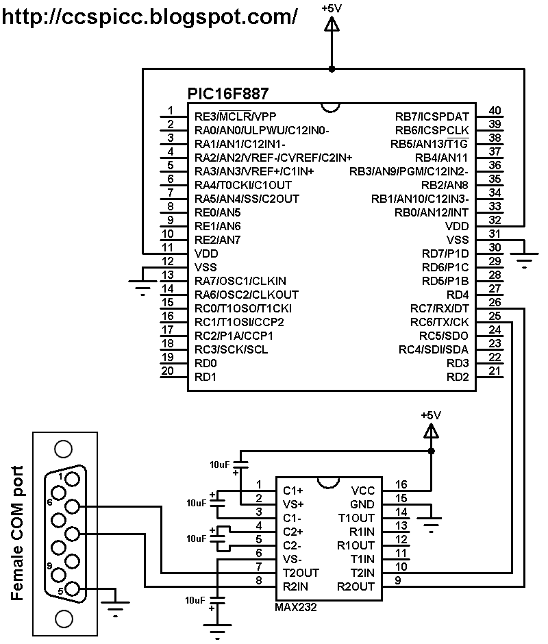
The tiny microcontroller PIC12F1822 has a built-in hardware UART module which allows us to easily transmit and receive data. This topic shows a simple UART example using CCS PIC C compiler. In this example I'm going to send/receive data to/from the PC over RS232. Hardware Required:
To interface the PIC12F1822 MCU with the PC we need MAX232 signal
level converter as shown in the circuit diagram. There are 2 lines
between the PIC12F1822 and the MAX232 and also two lines between the
MAX232 and the female COM connector. One line for data transmit and the
other one for data receive. The PIC12F1822 is configured in the C code (default configuration) so that the UART module RX function is on pin RA1 and TX function is on pin RA0.
The female COM connector is connected
to the PC using RS232 cable, this cable has to be male-female because
the PC RS232 port type is male.
In this example the PIC12F1822 MCU runs with its internal oscillator and MCLR pin function is disabled. UART Example for PIC16F84A microcontroller C code:
The function #use rs232(UART1, baud = 9600) is used to configure the UART protocol. Here the hardware UART module is used.
where:
9600 is the baud rate.
The functions used in the C code are: printf: sends a string of characters over RS232 transmission pin (TX). putc: send a character over RS232 transmission pin (TX). if(kbhit()): test if a character is ready for getc() function. getc(): read the character.
Complete C code for CCS C compiler is below.
/* PIC12F1822 UART example with CCS C compiler. http://ccspicc.blogspot.com/ electronnote@gmail.com*/#include <12F1822.h>
#fuses NOMCLR INTRC_IO PLL_SW
#usedelay(clock=32000000)
#use rs232(UART1, baud = 9600)
constchar message[] = "PIC12F1822 microcontroller UART example" ;
int8 i = 0, j;
void main() {
setup_oscillator(OSC_8MHZ | OSC_PLL_ON); // Set internal oscillator to 8MHz with PLL enabled (32MHz)
delay_ms(2000); // Wait 2 seconds// Print text
printf("\r"); // Set cursor to first position
printf("Hello world!");
// Print list of characters
printf("\n\r"); // Start new linewhile(message[i] != '\0'){
putc(message[i]); // Write character
delay_ms(100); // Wait 100 ms
i++; // Increment i
}
// Print numbers
printf("\n\r"); // Start new linefor(i = 0; i < 21; i++){
printf("%u\n\r", i); // Print i and start new line
delay_ms(500);
}
// Receive and send data over UARTwhile(TRUE){
if(kbhit()){ // If a character available
j = getc(); // UART read
putc(j); // Send it back
}
}
}
This topic shows a simple interfacing of 2 GB micro SD card with PIC16F84A microcontroller.
I used the PIC16F84A to read the SD card raw data which doesn't require a microcontroller with high RAM or ROM. In this interfacing I used software SPI because the PIC16F84A doesn't have a built-in hardware SPI module.
In this example there is no need for file systems (FAT16, FAT32 ...) because we're dealing with raw data which stored in the SD card memory spaces.
CCS IDE serial monitor is used to display the data after reading it and here the UART protocol is used. I used software UART because the PIC16F84A also does not have a UART module.
the link below shows a small PIC16F84A MCU UART example: Software UART for PIC16F84A microcontroller
In this project I used the MMC/SD card driver for CCS C compiler which is described in the post at the link below: MMC/SD Card driver for CCS PIC C compiler
The PIC16F84A MCU has only 68 bytes of data RAM which
means that it is not possible to load an entire sector of
512 bytes, but we can read many sectors byte by byte. Hardware Required:
PIC16F84A microcontroller
8 MHz crystal
2 x 22pF ceramic capacitors
SD Card
AMS1117 3.3V voltage regulator
3 x 3.3K ohm resistor
3 x 2.2K ohm resistor
2 x 10K ohm resistor
5 x 10uF polarized capacitor
100nF ceramic capacitor
MAX232 chip
Female RS232 connector
Male-female RS232 cable
5V Power source
Breadboard
Jumper wires
Interfacing SD card with PIC16F84A MCU circuit:
The AMS1117 3.3V voltage regulator is used to supply the SD card with
3.3V. Also, 3 voltage dividers are used to step down the 5V which comes
from the microcontroller to about 3V which is sufficient for the SD
card. Each voltage divider consists of 2K2 and 3K3 resistors.
The MISO of the SD card is connected directly to the microcontroller.
MAX232
integrated circuit is used to interface the microcontroller with the
PC, I connected just one wire (RB3) because I need to transmit data from
the SD card to the microcontroller and then from the microcontroller to
the PC, there is no need to connect the second wire because I don't
have to send data from the PC to the microcontroller.
In this project the PIC16F84A MCU runs with 8MHz crystal oscillator. SD Card raw data read using PIC16F84A CCS C code:
The C code below was tested with CCS PIC C compiler version 5.051.
Software SPI is used to interface the MCU with the SD card with 4 data lines: SDI, SDO, SCL and CS.
The code below reads the SD card sector 0, sector size is 512 bytes. To be able to read the whole sector I used the function sdcard_read_byte which allows me to read any byte located in the SD card. For example the function sdcard_read_byte(200, &value); reads the byte of address 200 and saves its data (1 byte) in the variable pointer value.
The functions sdcard_init and sdcard_read_byte return 0 if OK, non-zero if error. Complete C code is below.
// Interfacing PIC16F84A with SD card CCS C code.// http://ccspicc.blogspot.com/// electronnote@gmail.com// SD Card module connections#define SDCARD_PIN_SDI PIN_B7
#define SDCARD_PIN_SCL PIN_B6
#define SDCARD_PIN_SDO PIN_B5
#define SDCARD_PIN_SELECT PIN_B4
// End SD card module connections#include <16F84A.h>
#fuses HS,NOWDT,PUT,NOPROTECT
#usedelay(clock = 8000000)
#use fast_io(B)
#use rs232(xmit = PIN_B3, rcv = PIN_B2, baud = 9600)
#include <sdcard.c> // SD Card driver source fileint8 value;
int16 i;
void main() {
output_drive(PIN_B3); // Configure pin RB3 as output
printf("\r"); // Set cursor to first position
printf("Read Sector 0:");
printf("\n\r"); // Start new lineif(sdcard_init() == 0){ // Initialize the SD card; returns 0 if OK, non-zero if error
printf("Card init OK");
printf("\n\r"); // Start new linefor(i=0; i<512;i++){ // Read sector byte-by-byte (total: 512 bytes)
sdcard_read_byte(i, &value);
printf("%X", value); // Print 'value' with hexadecimal format
}
}
printf("\n\r"); // Start new line
printf("End.");
}
The microcontroller PIC16F84A has no hardware UART module, but we can use software UART to send/receive data to/from the PC via RS232 cable (COM port). This topic shows a simple example for the use of the UART protocol with the PIC16F84A MCU. Hardware Required:
UART Example for PIC16F84A microcontroller circuit:
To interface the PIC16F84A MCU with the PC we need MAX232 signal level converter as shown in the circuit diagram. There are 2 lines between the PIC16F84A and the MAX232 and also two lines between the MAX232 and the female COM connector. One line for data transmit and the other one for data receive.
The female COM connector is connected to the PC using RS232 cable, this cable has to be male-female because the PC RS232 port type is male.
In this example the PIC16F84A MCU runs with 8MHz crystal oscillator. UART Example for PIC16F84A microcontroller C code:
The function #use rs232(xmit = PIN_B4, rcv = PIN_B5, baud = 2400) is used to configure the UART protocol. Here software UART is used.
where:
xmit is the transmit pin (RB4)
rcv is the receive pin (RB5)
2400 is the baud rate.
The functions used in the C code are: printf: sends a string of characters over RS232 transmission pin (TX). putc: send a character over RS232 transmission pin (TX). getc(): read character if available.
Complete C code for CCS C compiler is below.
// Software UART example for PIC16F84A.// http://ccspicc.blogspot.com/// electronnote@gmail.com#include <16F84A.h>
#fuses HS, NOWDT, PUT, NOPROTECT
#usedelay(clock = 8000000)
#use fast_io(B)
#use rs232(xmit = PIN_B4, rcv = PIN_B5, baud = 2400)
constchar message[] = "***** PIC16F84A microcontroller UART example *****" ;
int8 i = 0, j;
void main(){
output_drive(PIN_B4);
delay_ms(2000); // Wait 2 seconds// Print text
printf("Hello world!");
// Print list of characters
printf("\n\r"); // Start new linewhile(message[i] != '\0'){ // Loop until the end of the string
putc(message[i]); // Write character
delay_ms(100); // Wait 100 ms
i++; // Increment i
}
// Print numbers
printf("\n\r"); // Start new linefor(i = 0; i < 21; i++){
printf("%u\n\r", i); // Print i and start new line
delay_ms(500);
}
// Receive and send character via UARTwhile(TRUE){
j = getc(); // UART read character
putc(j); // Send it back
}
}
After reading raw data (bytes and sectors) from SD card, now I'm going to use FAT16 file system to read and print text file located in 2 GB SD card.
Read SD card raw data topic: MMC/SD Card raw data read with PIC16F887 microcontroller
UART protocol is used to display the content of the text file.
For this project, I used MMC/SD card driver for CCS C compiler which can be found in: MMC/SD Card driver for CCS PIC C compiler
And I used FAT16 library (for reading files) for CCS C compiler which can be downloaded from: FAT16 Library for CCS C compiler
Hardware Required:
PIC16F887 microcontroller
FAT16 formatted MMC/SD card ( <= 2 GB)
ASM1117 3.3 voltage regulator
3 x 3.3K ohm resistor
3 x 2.2K ohm resistor
10K ohm resistor
5 x 10uF polarized capacitor
100nF ceramic capacitor
MAX232 chip
Female COM port
5V Power source
Breadboard
Jumper wires
Read text files from FAT16 SD card with PIC16F887 circuit:
As known the SD card voltage is 3.3V and the PIC16F887 voltage is
5V, so AMS1117 3.3V is used to step down the 5V in order to supply our
SD card with 3.3V. Also each digital output pin of the PIC16F887 MCU can be logic 0 (0V) or logic 1
(5V) and connecting the microcontroller output pins (CS , SDO and SCK)
directly to the SD card may damage it, here a voltage divider is used
to get about 3V from the 5V which is enough for the SD card. The voltage
divider consists of 3.3K and 2.2 K resistors. The MISO is connected
directly to the SDI pin of the microcontroller because it is the data
output pin of the SD card which is normally does not exceed 3.3V.
I
used just one wire (RD2) to transmit data from the microcontroller to
the PC (there is no need for the MCU to receive data so the receiving
wire is not connected).
The chip select pin of the SD card is connected to pin RD3 (the SD card chip select pin is active low).
In this project the PIC16F887 MCU uses its internal oscillator and MCLR pin function is disabled. Read text files from FAT16 SD card with PIC16F887 C code:
The C code below was tested with CCS C compiler version 5.051.
SD card driver and FAT16 library for CCS must be added to the
project, just by putting the two source codes in the project folder or the
CCS driver folder.
In this example I used the hardware SPI module
of the PIC16F887, software SPI also works but the hardware one
is much faster.
I named the text file
"mytext" (basically it is mytext.txt) but in the CCS C code we've to
add the extension of the file which becomes "mytext.txt".
I used a read buffer of 10 bytes ( file_data[10] ), so the
microcontroller reads the text file 10 bytes by 10 bytes, it reads 10
bytes and send it to the PC via RS232 then the second 10 bytes and so on
until the function fat16_read_data(10, file_data) returns 1 which means we're at the end of the file.
The functions used in the C code are: fat16_init(): initializes the SD card and the FAT16 file system, return 0 if OK and 1 if error. fat16_open_file(txt): opens file with predefined name. fat16_read_data(10, file_data): read data (10 bytes) from the opened file and save it in the array file_data. printf: outputs data over RS232 where printf("%s", file_data); outputs a string of characters (file_data).
Complete C code is below.
/* Read and print text file from FAT16 microSD card using PIC16F887 MCU. Fat16 library and MMC/SD card driver for CCS C compiler must be installed http://ccspicc.blogspot.com/ electronnote@gmail.com*/// SD Card module connections#define SDCARD_SPI_HW // Hardware SPI module is used for the SD card#define SDCARD_PIN_SELECT PIN_D3 // SD card chip select pin is connected to pin RD3// End SD card module connections#include <16F887.h>
#fuses NOMCLR, INTRC_IO, NOBROWNOUT, NOLVP
#usedelay(clock = 8MHz)
#use rs232(xmit = PIN_D2, rcv = PIN_D1, baud = 9600)
#include <sdcard.c> // SD card diver source file#include <fat16.c> // FAT16 Library source fileint8 file_data[10];
void open_file(){
constint8 *txt = "mytext.txt"; // File name 'mytext.txt'if(fat16_open_file(txt) == 0){
printf("OK!");
printf("\n\r"); // Start new linewhile(fat16_read_data(10, file_data) == 0) // Read file data
printf("%s", file_data); // Print file data as stringreturn;
}
printf("\n\r"); // Start new line
printf("File opening error!");
}
void main(){
setup_oscillator(OSC_8MHZ); // Set internal oscillator to 8MHz
set_tris_d(0); // Configure PORTD pins as outputs
delay_ms(2000);
printf("\n\r"); // Start new line
printf("*** Read text file from FAT16 SD card using PIC16F887 ***");
delay_ms(2000);
printf("\n\r"); // Start new line
printf("Initializing FAT16 library ...... ");
if(fat16_init() == 0){ // If FAT16 file system and SD card were successfully initialized
printf("OK!");
delay_ms(2000);
printf("\n\r"); // Start new line
printf("Opening file: 'mytext.txt'...... ");
open_file();
}
else { // Problem occured while the initialization
printf("\n\r"); // Start new line
printf("Initialization error!");
}
printf("\n\r"); // Start new line
printf("*** END ***");
while(TRUE) ; // Endless loop
}
After finishing the project, I got a result similar to the one shown in the video below where the used microcontroller is PIC16F877A.
This small example shows how to read SD card raw data (bytes, sectors ...). SD card raw data means that there is no use of system files like FAT16 or FAT32. Serial monitor is used to display the data after reading it and here the UART protocol is used.
the link below shows a small PIC16F887 MCU UART example: UART Example for PIC16F887 microcontroller using CCS PIC C compiler
In this project I used the MMC/SD card driver for CCS C compiler which is described in the post at the link below: MMC/SD Card driver for CCS PIC C compiler
The PIC16F887 MCU has only 368 bytes of data RAM which
means that it is not possible to load an entire sector of
512 bytes. That means we can't write byte or sector correctly with this
microcontroller unless an external component is added to the circuit
such as external EEPROM which of course slows the writing process. But
reading is not like writing, we can read all the SD card data byte by
byte. Hardware Required:
PIC16F887 microcontroller
SD Card
AMS1117 3.3V voltage regulator
3 x 3.3K ohm resistor
3 x 2.2K ohm resistor
10K ohm resistor
5 x 10uF polarized capacitor
100nF ceramic capacitor
MAX232 chip
Female COM port
5V Power source
Breadboard
Jumper wires
Interfacing SD card with PIC16F887 MCU circuit:
The AMS1117 3.3V voltage regulator is used to supply the SD card with
3.3V. Also 3 voltage dividers are used to step down the 5V which comes
from the microcontroller to about 3V which is sufficient for the SD
card. Each voltage divider consists of 2K2 and 3K3 resistors.
MAX232
integrated circuit is used to interface the microcontroller with the
PC, I connected just one wire (RD2) because I need to transmit data from
the SD card to the microcontroller and then from the microcontroller to
the PC, there is no need to connect the second wire because I don't
have to send data from the PC to the microcontroller.
Hardware SPI module is used by the microcontroller to read data from the SD card, the SPI pins of the PIC16F887 are:
SCK (RC3): connected to pin SCK of the SD card
SDI (RC4): connected to pin MISO of the SD card
SD0 (RC5): connected to pin MOSI of the SD card
and there is an other pin which is CS (Chip Select) can be
connected to any digital output pin (defined in the code), this pin is
connected to SS pin of the SD card. SD Card raw data read using PIC16F887 CCS C code:
The C code below was tested with CCS PIC C compiler version 5.051.
There are two functions in the code: sdcard_read_byte and sdcard_read_data.
I used the first function to read byte with address 0 and I used the
second function to read sector number 0. Since the PIC16F887 has only
368 bytes of RAM, I can not upload all the sector data (512 bytes) in
one time, I divided the sector into 16 32-byte parts, so 16 x 32 = 512.
The sdcard_read_data function allows us to read data from the SD card starting from any address with any size we want.
The functions sdcard_init , sdcard_read_byte and sdcard_read_data return 0 if OK and non-zero if an error has been occurred.
// Interfacing PIC16F887 microcontroller with SD card CCS C code.// This example shows raw data read of the SD card.// This example does not use any file system (FAT16, FAT32 ...).// MMC/SD card driver for CCS C compiler must be installed!// http://ccspicc.blogspot.com/// electronnote@gmail.com// SD Card module connections#define SDCARD_SPI_HW // Hardware SPI module is used for the SD card#define SDCARD_PIN_SELECT PIN_D3 // SD card chip select pin is connected to pin RD3// End SD card module connections#include <16F887.h>
#fuses NOMCLR, INTRC_IO, NOBROWNOUT, NOLVP
#usedelay(clock = 8MHz)
#use rs232(xmit = PIN_D2, rcv = PIN_D1, baud = 9600)
#include <sdcard.c> // SD card diver source fileint8 i, j, one_byte, _data[32], size = 32;
void main(){
setup_oscillator(OSC_8MHZ); // Set internal oscillator to 8MHz
set_tris_d(0); // Configure PORTD pins as outputs
delay_ms(2000);
printf("\n\r"); // Start new line
printf("*** Interfacing PIC16F887 MCU with SD card ***");
printf("\n\r"); // Start new line
printf("Initializing the SD card...");
printf("\n\r"); // Start new line
i = sdcard_init(); // Initialize the SD card moduleif(i == 0){ // If the SD card has been successfully initialized// Read 1 single byte
printf("Read byte with address 0:");
printf("\n\r"); // Start new line
delay_ms(2000);
if(sdcard_read_byte(0, &one_byte) == 0)
printf("%X\n\r", one_byte); // Print the value of 'one_byte'// Read 1 sector
printf("Read sector 0:"); // Sector 0 from address 0 to 511 (512 bytes)
printf("\n\r"); // Start new line
delay_ms(2000);
for( i = 0; i < 16; i++){
if(sdcard_read_data((int32)i * size, size, _data) == 0){
for(j = 0; j < 32; j++)
printf("%X", _data[j]); // Print 32 byte of data
}
}
}
// End
printf("\n\r"); // Start new line
printf("*** END ***");
while(TRUE) ; // Endless loop
}
After compiling the code and burning the HEX file into the
microcontroller and with the help of the Serial Monitor of the CCS C IDE
I got the result shown in the image below (I used a SD card with 2 GB).
PIC18F4550 microcontroller with FAT16 microSD card
After I successfully read/wrote raw data from/to an SD card I want to read and display text files from the SD card. I did this with the SD card driver and FAT16 library for CCS C compiler. The SD card driver can be found on this topic: MMC/SD Card driver for CCS PIC C compiler
and FAT16 file system library can be downloaded from this topic: FAT16 Library for CCS C compiler
With these libraries we can easily open and print text files located in FAT16 formatted SD card. To format an SD card with FAT16 file system, the card capacity must be <= 2 GB.
To see how to read/write raw data (bytes, sectors ....) from/to SD card read the following topic: SD Card byte/sector read and write with PIC18F4550 microcontroller Hardware Required:
PIC18F4550 microcontroller
FAT16 formatted SD card
ASM1117 3.3 voltage regulator
8 MHz crystal oscillator
2 x 22pF ceramic capacitors
3 x 3.3K ohm resistor
3 x 2.2K ohm resistor
10K ohm resistor
5 x 10uF polarized capacitor
100nF ceramic capacitor
MAX232 chip
Female COM port
5V Power source
Breadboard
Jumper wires
Interfacing PIC18F4550 with SD card circuit:
As known the SD card voltage is 3.3V and the PIC18F4550 voltage is
5V, so AMS1117 3.3V is used to step down the 5V in order to supply our
SD card. Also the outputs of the PIC18F4550 are logic 0 (0V) or logic 1
(5V) and connecting the microcontroller output pins (CS , SDO and SCK)
directly to the SD card may damage it, here a voltage divider is used
to get about 3V from the 5V which is enough for the SD card. The voltage
divider consists of 3.3K and 2.2 K resistors. The MISO is connected
directly to the SDI pin of the microcontroller because it is the data
output pin of the SD card which is normally does not exceed 3.3V.
The MAX232 is used to interface our microcontroller with PC via serial port as what was done in this topic: CCS C UART example for PIC18F4550 microcontroller
I
used just one wire (RD2) to transmit data from the microcontroller to
the PC (there is no need for the MCU to receive data so the receiving
wire is not connected).
The chip select pin of the SD card is connected to pin RD3 (the SD card chip select pin is active low). Read and display text file from FAT16 microSD card using PIC18F4550 C code:
The C code below was tested with CCS PIC C compiler versions 5.051 and 5.070.
The microcontroller runs at 48MHz (8MHz + PLL).
SD card driver and FAT16 library for CCS must be added to the project, just by putting the two source codes in the project folder or the CCS driver folder.
In this example I used the hardware SPI module of the PIC18F4550, software SPI also can be used but the hardware one is much faster.
The functions used in the C code are: fat16_init(): initializes the SD card and the FAT16 file system, return 0 if OK and 1 if error. fat16_open_file(txt): opens file with predefined name. fat16_read_data(512, file_data): read data (512 bytes) from the opened file and save it in the array file_data. printf: outputs data over RS232 where printf("%s", file_data); outputs a string of characters (file_data).
// Read and display text file from FAT16 SD card using PIC18F4550.// Fat16 library and MMC/SD card driver for CCS C compiler must be installed!// http://ccspicc.blogspot.com/// electronnote@gmail.com// SD Card module connections#define SDCARD_SPI_HW
#define SDCARD_PIN_SELECT PIN_D3
// End SD card module connections#include <18F4550.h>
#fuses NOMCLR HSPLL PLL2 CPUDIV1
#usedelay(clock = 48MHz)
#use fast_io(D)
#use rs232(xmit = PIN_D2, rcv = PIN_D1, baud = 9600)
#include <sdcard.c> // SD card diver source code#include <fat16.c> // FAT16 library source fileconstint8 *txt = "mytext.txt"; // File name 'mytext.txt'int8 file_data[512];
void main(){
set_tris_d(0); // Configure PORTD pins as outputs
delay_ms(2000);
printf("\n\r"); // Start new line
printf("*** Read text file from FAT16 SD card using PIC18F4550 ***");
delay_ms(2000);
printf("\n\r"); // Start new line
printf("Initializing FAT16 library ...... ");
if(fat16_init() == 0){ // If FAT16 file system and SD card were successfully initialized
printf("OK!");
delay_ms(2000);
printf("\n\r"); // Start new line
printf("Opening file: 'mytext.txt'...... ");
if(fat16_open_file(txt) == 0){
printf("OK!");
printf("\n\r"); // Start new linewhile(fat16_read_data(512, file_data) == 0) // Read file data
printf("%s", file_data); // Print file data as string
}
else {
printf("\n\r"); // Start new line
printf("File opening error!");
}
}
else { // Problem occured while the initialization
printf("\n\r"); // Start new line
printf("Initialization error!");
}
printf("\n\r"); // Start new line
printf("*** END ***");
while(TRUE) ; // Endless loop
}
After the connection of the circuit and the burning of the HEX file into the PIC18F4550 using PICKit 3 programmer, I got the result as shown in the video below:
The microcontroller PIC16F887 has a build in USART (Universal Synchronous/Asynchronous Receiver/Transmitter) module. This module can be used as UASAT or UART.
This small post shows an example for the usage of the UART protocol with PIC16F887 microcontroller. Hardware Required:
In this example the microcontroller PIC16F887 uses its internal oscillator and MCLR pin function is disabled.
The female COM port is connected to the PC using RS232 cable, this cable has to be male-female because the PC COM port is male. UART Example for PIC16F887 CCS C code:
The code used in this example is shown below.
The function #use rs232(UART1, baud = 9600) is used to configure the UART protocol. Here the hardware UART module is used. If the pins TX and RX (RC6 and RC7) are used by an other application we can use software UART. Software UART is generated by the compiler with the same previous function. For example TX is mapped to pin RD0 and RX to pin RD1: #use rs232(xmit = PIN_D0, rcv = PIN_D0, baud = 9600)
where 9600 is the baud rate.
The functions used in the C code are: printf: sends a string of characters over RS232 transmission pin (TX). putc: send a character over RS232 transmission pin (TX). if(kbhit()): test if a character is ready for getc() function. getc(): read the character.
// CCS C UART example for PIC16F887 microcontroller// http://ccspicc.blogspot.com/// electronnote@gmail.com#include <16F887.h>
#fuses NOMCLR, INTRC_IO, NOBROWNOUT, NOLVP
#usedelay(clock = 8MHz)
#use rs232(UART1, baud = 9600)
constchar message[] = "PIC16F887 microcontroller UART example" ;
int8 i = 0, j;
void main(){
setup_oscillator(OSC_8MHZ); // Set internal oscillator to 8MHz
delay_ms(2000); // Wait 2 seconds// Print text
printf("Hello world!");
// Print list of characters
printf("\n\r"); // Start new linewhile(message[i] != '\0'){
putc(message[i]); // Write character
delay_ms(100); // Wait 100 ms
i++; // Increment i
}
// Print numbers
printf("\n\r"); // Start new linefor(i = 0; i < 21; i++){
printf("%u\n\r", i); // Print i and start new line
delay_ms(500);
}
// Receive and send data via UARTwhile(TRUE){
if(kbhit()){ // If a character available
j = getc(); // UART read
putc(j); // Send it back
}
}
}
After I build the circuit and burned the HEX file into the PIC16F887 using PICkit 3 programmer, I got a result as shown in this video (using CCS C Compiler IDE Serial Monitor tool):
Using MMC/SD card driver and FAT16 library for CCS C compiler we can read files from FAT16 formatted SD card using SPI protocol.
This topic shows how to read and display a text file from SD card using PIC16F877A microcontroller and CCS PIC C compiler.
UART protocol will be used to display the content of the text file. Simply the text file which I'm going to display is the source code of this project.
First we need the SD card driver which can be downloaded from the following topic: MMC/SD Card driver for CCS PIC C compiler
and FAT16 file system library can be downloaded from this topic: FAT16 Library for CCS C compiler
Hardware Required:
PIC16F877A microcontroller
FAT16 Formatted SD card (<= 2 GB) with text file
ASM1117 3.3 voltage regulator
20 MHz crystal oscillator
2 x 22pF ceramic capacitors
3 x 3.3K ohm resistor
3 x 2.2K ohm resistor
2 x 10K ohm resistor
5 x 10uF polarized capacitor
100nF ceramic capacitor
MAX232 chip
Female COM port
5V Power source
Breadboard
Jumper wires
The circuit:
The AMS1117 3.3V voltage regulator is used to supply the SD card with
3.3V. Also 3 voltage dividers are used to step down the 5V which comes
from the microcontroller to about 3V which is sufficient for the SD
card. Each voltage divider consists of 2K2 and 3K3 resistors.
MAX232
integrated circuit is used to interface the microcontroller with the
PC, I connected just one wire (RD2) because I need to transmit data from
the SD card to the microcontroller and then from the microcontroller to
the PC, there is no need to connect the second wire because I don't
have to send data from the PC to the microcontroller.
Hardware SPI is used by the microcontroller to read data from the SD card, the SPI pins of the PIC16F877A are:
SCK (RC3): connected to pin SCK of the SD card
SDI (RC4): connected to pin MISO of the SD card
SD0 (RC5): connected to pin MOSI of the SD card
and there is an other pin which is CS (Chip Select) can be
connected to any digital output pin (defined in the code), this pin is
connected to SS pin of the SD card.
Read text file from SD card with FAT16 file system using PIC16F877A C code:
The code used for this example is shown below. It was tested with CCS PIC C compiler versions 5.051 and 5.070.
The text file which I used is just the code below, I named it in Windows "mytext" (basically it is mytext.txt) but in the CCS C code we've to add the extension of the file which becomes "mytext.txt".
I used a read buffer of 10 bytes ( file_data[10] ), so the microcontroller reads the text file 10 bytes by 10 bytes, it reads 10 bytes and send it to the PC via RS232 then the second 10 bytes and so on until the function fat16_read_data(10, file_data) returns 1 which means we're at the end of the file.
I used the command printf("%s", file_data) to display file data as string.
// Read text file from SD card with FAT16 file system CCS C code.// Used microcontroller: PIC16F877A// Fat16 library and MMC/SD card driver for CCS C compiler must be installed!// Use at your own risk!// http://ccspicc.blogspot.com/// electronnote@gmail.com// SD Card module connections#define SDCARD_SPI_HW
#define SDCARD_PIN_SELECT PIN_D3
// End SD card module connections#include <16F877A.h>
#fuses HS,NOWDT,NOPROTECT,NOLVP
#usedelay(clock = 20000000)
#use fast_io(D)
#use rs232(xmit = PIN_D2, rcv = PIN_D1, baud = 9600)
#include <sdcard.c> // SD card diver source code#include <fat16.c>
int8 file_data[10];
void open_file(){
constint8 *txt = "mytext.txt"; // File name 'mytext.txt'if(fat16_open_file(txt) == 0){
printf("OK!");
printf("\n\r"); // Start new linewhile(fat16_read_data(10, file_data) == 0) // Read file data
printf("%s", file_data); // Print file data as stringreturn;
}
printf("\n\r"); // Start new line
printf("File opening error!");
}
void main(){
set_tris_d(0); // Configure PORTD pins as outputs
delay_ms(2000);
printf("\n\r"); // Start new line
printf("*** Read text file from FAT16 SD card using PIC16F877A ***");
delay_ms(2000);
printf("\n\r"); // Start new line
printf("Initializing FAT16 library ...... ");
if(fat16_init() == 0){ // If FAT16 file system and SD card were successfully initialized
printf("OK!");
delay_ms(2000);
printf("\n\r"); // Start new line
printf("Opening file: 'mytext.txt'...... ");
open_file();
}
else { // Problem occured while the initialization
printf("\n\r"); // Start new line
printf("Initialization error!");
}
printf("\n\r"); // Start new line
printf("*** END ***");
while(TRUE) ; // Endless loop
}
The following video shows the output:
If there is no card inserted I got the following result:
and if there is no "mytext.txt" file in the SD card I got this result:
With the help of the small driver of the MMC/SD cards we can easily read and write any sector and any byte located in the media. First download the SD card driver from the topic below and after the download put the file sdcard.c in the project folder: MMC/SD Card driver for CCS PIC C compiler
In this project a 8 GB SDHC card is used (SD card capacity is not important), the SD card is connected to the PIC18F4550 microcontroller via hardware SPI and the microcontroller runs with a frequency of 48MHz (8MHz with PLL). Circuit schematic is shown below. Hardware Required:
PIC18F4550 microcontroller
SD Card
AMS1117 3.3V voltage regulator
8MHz crystal oscillator
2 x 22pF ceramic capacitor
3 x 3.3K ohm resistor
3 x 2.2K ohm resistor
10K ohm resistor
100nF ceramic capacitor
MAX232
5 x 10uF polarized capacitor
Female COM port
5V Power source
Breadboard
Jumper wires
As known the SD card voltage is 3.3V and the PIC18F4550 voltage is 5V, so AMS1117 3.3V is used to step down the 5V in order to supply our SD card. Also the outputs of the PIC18F4550 are logic 0 (0V) or logic 1 (5V) and connecting the microcontroller output pins (CS , SDO and SCK) directly to the SD card will damage it, here a voltage divider is used to get about 3V from the 5V which is enough for the SD card. The voltage divider consists of 3.3K and 2.2 K resistors. The MISO is connected directly to the SDI pin of the microcontroller because it is the data output pin of the SD card which is normally does not exceed 3.3V.
The MAX232 is used to interface our microcontroller with PC via serial port as what was done in this topic: CCS C UART example for PIC18F4550 microcontroller
I used just one wire (RD2) to transmit data from the microcontroller to the PC (there is no need for the MCU to receive data so the receiving wire is not connected).
The chip select pin of the SD card is connected to pin RD3 (the SD card chip select pin is active low).
It is recommended to use voltage level translator (level shifter) instead of the voltage divider if it is available. The level translator translates the 5V to 3.3V for CS (SS), SDO (MOSI), and SCK and translates the 3.3V of MISO to 5V (PIC18F4550 SDI is an input with Schmitt buffer which needs 0.8VDD for high input). For example we can use chips like 74LVC04 (hex NOT) or 74LVC125A (quadruple buffer) to go from 5V to 3.3V and 74HCT245 to go from 3.3V to 5V.
For my hardware circuit I used both the level translator using 74LVC04 and74HCT245 and also the voltage divider using resistors as shown in the circuit schematic above, both circuits worked very well.
SD Card byte/sector read and write with PIC18F4550 microcontroller CCS C code:
This is our example C code, this code was tested with versions 5.051 and 5.070.
The microcontroller runs at 48MHz (8MHz + PLL).
The MMC/SD card driver file must be added as mentioned above. This example is tested in real hardware circuit as well as simulation using Proteus ISIS. After writing sectors or bytes you can check it with some softwares like: Hex Workshop, HxD Hex editor......
Before you test your hardware circuit make sure that your MMC/SD card does not contain any important files!
// Interfacing PIC18F4550 microcontroller with SD card (SDHC) CCS C code.// This example shows read and write functions of a single byte and whole sector.// This example does not use any file system (FAT16, FAT32 ...).// MMC/SD card driver for CCS C compiler must be installed!// Use at your own risk!// http://ccspicc.blogspot.com/// electronnote@gmail.com// SD Card module connections#define SDCARD_SPI_HW
#define SDCARD_PIN_SELECT PIN_D3
// End SD card module connections#define SDCARD_WRITE // Enable write data to media functions#include <18F4550.h>
#fuses NOMCLR HSPLL PLL2 CPUDIV1
#usedelay(clock = 48MHz)
#use fast_io(B)
#use fast_io(D)
#use rs232(xmit = PIN_D2, rcv = PIN_D1, baud = 9600)
#include <sdcard.c> // SD card diver source codeint8 one_byte, sector_data[512];
int16 i;
void main(){
set_tris_b(1); // Configure RB0 pin as an input pin
set_tris_d(0); // Configure PORTD pins as outputs
delay_ms(2000);
printf("\n\r"); // Start new line
printf("*** Interfacing PIC18F4550 with SD card ***");
printf("\n\r"); // Start new line
printf("Initializing the SD card...");
printf("\n\r"); // Start new line
i = sdcard_init(); // Initialize the SD card moduleif(i == 0){ // If the SD card has been successfully initialized// Read 1 single byte
printf("Read byte with address 0:");
printf("\n\r"); // Start new line
delay_ms(2000);
if(sdcard_read_byte(0, &one_byte) == 0)
printf("%X\n\r", one_byte); // Print the value of 'one_byte'// Read 1 sector
printf("Read sector 0:");
printf("\n\r"); // Start new line
delay_ms(2000);
if(sdcard_read_sector(0, sector_data) == 0)
for(i = 0; i < 512; i++)
printf("%X", sector_data[i]); // Print all sector bytes (512 bytes)// Write 1 sector
printf("\n\r"); // Start new line
printf("Write sector 3:");
printf("\n\r"); // Start new line
delay_ms(2000);
if(sdcard_write_sector(3, sector_data) == 0)
printf("Write sector OK");
// Write 1 byte
printf("\n\r"); // Start new line
printf("Write byte 0x700:");
printf("\n\r"); // Start new line
delay_ms(2000);
if(sdcard_write_byte(0x700, one_byte) == 0)
printf("Write byte OK");
// Read sector 3 (check the previous write sector and write byte functions)
printf("\n\r"); // Start new line
printf("Read sector 3:");
printf("\n\r"); // Start new line
delay_ms(2000);
if(sdcard_read_sector(3, sector_data) == 0)
for(i = 0; i < 512; i++)
printf("%X", sector_data[i]); // Print all sector bytes (512 bytes)// End
printf("\n\r"); // Start new line
printf("*** END ***");
}
while(TRUE) ; // Endless loop
}
After building circuit and code I get a result as shown in this video:
I opened the SD card with HxD Hex editor and I found sector 0 and sector 3 as shown below.
This is sector 0:
And this is sector 3 where the underlined byte which has address 0x700 is caused by the write_byte function:
As we can see sector 0 and sector 3 data are the same except byte 0x700, so what I did is I read all sector 0 data (512 bytes) and then I wrote these data into sector 3 and finally I wrote byte 0x700 with the value of byte 0x00 which I read in the first function (read_byte).
In this post we'll see how to read raw data from MMC or SD card using PIC16F877A microcontroller. Reading raw data is just the reading of bytes and sectors of the SD card. UART protocol is used to display the data.
SD card driver for CCS C compiler is used in this example, so download the driver from the following topic and put it in the project folder: MMC/SD Card driver for CCS PIC C compiler
The microcontroller PIC16F877A has only 368 bytes of data RAM which means that it is not possible to load an entire sector which contains 512 bytes. That means we can't write byte or sector correctly with this microcontroller unless an external component is added to the circuit such as external EEPROM which of course slows the writing process. But reading is not like writing, we can read all the SD card data byte by byte.
In this topic we will just read data from the SD card and send it to PC via UART protocol.
The following topic shows a simple example for the UART protocol and PIC16F877A microcontroller: PIC16F877A UART example Required components:
PIC16F877A microcontroller
SD Card
AMS1117 3.3V voltage regulator
8MHz crystal
2 x 22pF ceramic capacitors
3 x 3.3K ohm resistor
3 x 2.2K ohm resistor
2 x 10K ohm resistor
5 x 10uF polarized capacitor
100nF ceramic capacitor
MAX232 chip
Female COM port
5V Power source
Breadboard
Jumper wires
Interfacing PIC16F877A with SD card circuit:
In this project the PIC16F877A runs with 8MHz crystal oscillator and for higher data transfer rate use crystal with higher frequency up to 20MHz.
The AMS1117 3.3V voltage regulator is used to supply the SD card with 3.3V. Also 3 voltage dividers are used to step down the 5V which comes from the microcontroller to about 3V which is sufficient for the SD card. Each voltage divider consists of 2K2 and 3K3 resistors.
MAX232 integrated circuit is used to interface the microcontroller with the PC, I connected just one wire (RD2) because I need to transmit data from the SD card to the microcontroller and then from the microcontroller to the PC, there is no need to connect the second wire because I don't have to send data from the PC to the microcontroller.
Hardware SPI is used by the microcontroller to read data from the SD card, the SPI pins of the PIC16F877A are:
SCK (RC3): connected to pin SCK of the SD card
SDI (RC4): connected to pin MISO of the SD card
SD0 (RC5): connected to pin MOSI of the SD card
and there is an other pin which is CS (Chip Select) can be connected to any digital output pin (defined in the code), this pin is connected to SS pin of the SD card. SD Card raw data read using PIC16F877A CCS C code:
The code used for this example is shown below. It was tested with CCS PIC C compiler versions 5.051 and 5.070.
There are two functions in the code: sdcard_read_byte and sdcard_read_data. I used the first function to read byte with address 0 and I used the second function to read sector number 0. Since the PIC16F877A has only 368 bytes of RAM and I can not upload all the sector data (512 bytes) in one time, I divided the sector into 16 32-byte parts, so 16 x 32 = 512. The sdcard_read_data function allows us to read data from the SD card starting from any address with any size we want.
The functions sdcard_init , sdcard_read_byte and sdcard_read_data return 0 if OK and non-zero if an error has been occurred.
// Interfacing PIC16F877A microcontroller with SD card CCS C code.// This example shows raw data read of the SD card.// This example does not use any file system (FAT16, FAT32 ...).// MMC/SD card driver for CCS C compiler must be installed!// Use at your own risk!// http://ccspicc.blogspot.com/// electronnote@gmail.com// SD Card module connections#define SDCARD_SPI_HW
#define SDCARD_PIN_SELECT PIN_D3
// End SD card module connections#include <16F877A.h>
#fuses HS,NOWDT,NOPROTECT,NOLVP
#usedelay(clock = 8000000)
#use fast_io(D)
#use rs232(xmit = PIN_D2, rcv = PIN_D1, baud = 9600)
#include <sdcard.c> // SD card diver source codeint8 i, j, one_byte, _data[32], size = 32;
void main(){
set_tris_d(0); // Configure PORTD pins as outputs
delay_ms(2000);
printf("\n\r"); // Start new line
printf("*** Interfacing PIC16F877A with SD card ***");
printf("\n\r"); // Start new line
printf("Initializing the SD card...");
printf("\n\r"); // Start new line
i = sdcard_init(); // Initialize the SD card moduleif(i == 0){ // If the SD card has been successfully initialized// Read 1 single byte
printf("Read byte with address 0:");
printf("\n\r"); // Start new line
delay_ms(2000);
if(sdcard_read_byte(0, &one_byte) == 0)
printf("%X\n\r", one_byte); // Print the value of 'one_byte'// Read 1 sector
printf("Read sector 0:"); // Sector 0 from address 0 to 511 (512 bytes)
printf("\n\r"); // Start new line
delay_ms(2000);
for( i = 0; i < 16; i++){
if(sdcard_read_data((int32)i * size, size, _data) == 0){
for(j = 0; j < 32; j++)
printf("%X", _data[j]); // Print 32 byte of data
}
}
}
// End
printf("\n\r"); // Start new line
printf("*** END ***");
while(TRUE) ; // Endless loop
}
After compiling the code and burning the HEX file into the microcontroller and with the help of the Serial Monitor of the CCS C IDE I got the result shown in the image below (I used a SD card with 4 GB ==> SDHC card).