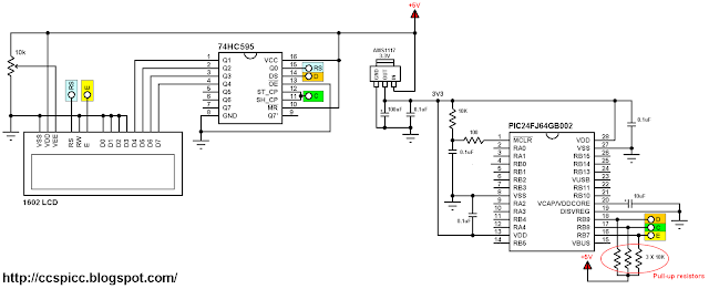
This post shows how to interface LCD screen (16x2, 20x'4 ....) with PIC24FJ64GB002 microcontroller where the compiler used is CCS C.
The PIC24FJ64GB002 is a 16-bit microcontroller runs with 3.3V while is the LCD used in this example is 5V. The PIC24FJ64GB002 has some 5.5V tolerant input pins (RB5, RB7, RB8, RB9, RB10 and RB11), with this pins we can apply 5V to the microcontroller without any problem.
An other good thing with this microcontroller is the open drain outputs, each output pin can be configured to work as an open drain output.
In this project I used a serial-in parallel-out shift register to minimize number of pins used by the LCD because we don't have enough 5.5V tolerant input pins to connect another 5V device. With the shift register the LCD will use only 3 pins which means we've gained at least 3 pins.
Hardware Required:
- PIC24FJ64GB002 microcontroller
- AMS1117 3V3 voltage regulator
- 16x2 LCD screen
- 74HC595 shift register (74HC164N and CD4094 also work)
- 100uF polarized capacitor
- 10uF polarized capacitor
- 4 x 0.1uF ceramic capacitor
- 4 x 10K ohm resistor
- 10K variable resistor
- 100 ohm resistor
- 5V power source
- Breadboard
- Jumper wires
In this example the PIC24FJ64GB002 MCU runs with its internal oscillator.
The AMS1117 3V3 voltage regulator is used to supply the MCU with 3.3V from the 5V source.
The E (Enable) pin of the LCD screen is connected directly to pin RB7 (#16) of the microcontroller. The C (Clock) pin of the shift register is connected to pin RB8 (#17) of the microcontroller. The last shift register pin which named D (Data) is connected to pin RB9 (#18) of the microcontroller.
The three pins: RB7, RB8 and RB9 are 5.5V tolerant input pins and can be configured to be an open drain outputs. With the open drain outputs and 5V pull up resistors we get what our LCD needs (logic 0 of 0V and logic 1 of 5V).
Interfacing PIC24FJ64GB002 with LCD C code:
The C code below was tested with CCS C compiler version 5.051.
To be able to compile the code below a 3-wire LCD driver has to be added to the project folder. Download link might be found in the post below:
3-Wire LCD driver for CCS PIC C compiler
I used the command set_open_drain_b(value) to configure the open-drain output pins of the PIC24FJ64GB002 MCU. For example if I want pin RB0 to be an open-drain output I just write:
set_open_drain_b(1);
For pins RB7, RB8 and RB9 I used:
set_open_drain_b(0x380);
where 0x380 = 896 = 0b0000001110000000
Complete C code is below.
// Interfacing PIC24FJ64GB002 with LCD example CCS C code
// Internal oscillator used @ 8 MHz
// http://ccspicc.blogspot.com/
// electronnote@gmail.com

// 3-Wire LCD module connections
#define LCD_DATA_PIN  PIN_B9
#define LCD_CLOCK_PIN PIN_B8
#define LCD_EN_PIN    PIN_B7
// End 3-Wire LCD module connections

#include <24FJ64GB002.h>
#fuses FRC NOWDT NOJTAG OSCIO SOSC_IO
#use delay(clock = 8M)
#include <3WireLCD.c>                  // 3-wire LCD source file

unsigned int8 i;
void main(){
  output_b(0);
  set_open_drain_b(0x380);             // Configure RB7, RB8 and RB9 pins as an open-drain outputs
  delay_ms(500);                       // Wait 1/2 second
  lcd_initialize();                    // Initialize LCD module
  lcd_cmd(LCD_CLEAR);                  // LCD Clear
  lcd_goto(3, 1);                      // Go to column 3 line 1
  lcd_out("Hello world!");
  delay_ms(1000);                      // Wait 1 second
  while(TRUE){
    for(i = 0; i < 200; ++i){
      lcd_goto(7, 2);                  // Go to column 7 row 4
      printf(lcd_out, "%3u", i);       // Write i with 3 numbers max
      delay_ms(500);
    }
  }
}


