Thursday, July 27, 2017

CDROM Sensored brushless DC motor drive with PIC16F887 microcontroller


BLDC Motor control using PIC16F887
In this blog there are some topics shows how to drive a cd-rom (dvd-rom) spindle motor using different types of PIC microcontrollers. This topic shows how to control the speed of a sensored BLDC motor using PIC16F887 microcontroller.
The BLDC motor is a three phase DC motor without brushes.
Basically there are two types of BLDC motors: sensored and sensorless. The sensored BLDC motor has 3 hall effect sensors which detect the rotor position while the sensorless BLDC motor has no hall effect sensors and it uses back emf to detect the rotor position.
The sensored BLDC motor is easy to drive because always we know the position of its rotor with the help of the hall effect sensors.
As mentioned above, the BLDC motor is a 3 phase DC motor which means it has 3 winding on the stator core. Two windings are excited at a time to create a rotating electric field. This method is fairly easy to implement, but to prevent the permanent magnet rotor from getting locked with the stator, the excitation on the stator must be sequenced in a specific manner while knowing the exact position of the rotor magnets.
3 phase BLDC motor coils
The sensored BLDC motor has 3 hall effect sensors (Sensor A, Sensor B and Sensor C) to sense rotor position, this sensors are placed as shown in the following picture. The motor which I'm going to drive has pinout as shown below (other motors may have another pinout).
In this motor each hall effect sensor has 4 pins: VCC, GND and two outputs (some sensors come with 3 pins: VCC, GND and output).
cd rom or dvd rom bldc motor pin configuration
Each sensor outputs a digital high for 180 electrical degrees and outputs a digital low for the other 180 electrical degrees. The following figure shows the relationship between the sensors outputs and the required motor drive voltages for phases A, B and C.
sensored bldc motor driving sequence
A three phase bridge is used to energize the BLDC motor windings.
3 phase inverter bridge for 3 phase bldc motor
According to the hall effect sensors, the 3 phase inverter bridge is controlled as shown in the following table:
bldc motor sequence table 
Hardware Required:
  • PIC16F887 microcontroller  -- datasheet
  • 20MHz crystal oscillator 
  • 2 x 22pF capacitor
  • Sensored BLDC motor
  • 10k ohm potentiometer
  • 2 x SN74LS08N  -- datasheet
  • SN74LS04N        -- datasheet
  • LM339 quad comparators -- datasheet
  • 3 x IRF4905 P-channel mosfet   -- datasheet
  • 3 x IRF3205 N-channel mosfet  -- datasheet
  • 3 x 2N2222A NPN transistor  -- datasheet
  • 6 x 22K ohm resistor
  • 6 x 10K ohm resistor
  • 4 x 100 ohm resistor
  • Protoboards
  • 12V voltage source
  • 5V voltage source
  • Jumper wires
CD-ROM Sensored brushless DC motor drive with PIC16F887 microcontroller circuit:
BLDC motor controller circuit (esc) using PIC16F887 microcontroller
In the circuit there are 3 comparators A, B and C (LM339) which are used with the hall effect sensors to detect rotor position. The complete circuit of the LM339 is shown below:
bldc motor hall effect sensors with LM339
Also in the circuit there are 8 AND and 3 NOT gates, and for that I used 2 x SN74LS08 (each one contains 4 AND gates) and one SN74LS04. The complete circuit of the three ICs is shown below:
SN74LS08 and SN74LS04 circuit
The two gates AND1 and AND2 are used to create two PWM signals from single PWM signal because PIC16F887 microcontroller has only two PWM modules and our project needs 3.
The other AND gates (AND3 - 8) and the NOT gates are used to drive the bridge mosfets and also provides a good protection to our mosfets because high and low mosfets of one line must not be ON at the same time.
A 10K ohm potentiometer is used to control the speed of the BLDC motor where its output is connected to AN0.
A 20MHZ crystal oscillator is used and MCLR pin function is disabled.
CD-ROM Sensored brushless DC motor drive with PIC16F887 microcontroller C code:
The following is code is for CCS PIC C compiler.
The potentiometer is used to vary the duty cycle of PWM1 and PWM2 signals which causes the speed of the BLDC motor to change. The outputs are controlled according to the following table:
bldc motor driving table
The two PWM modules of the PIC16F887 are used to generate two PWM signals. Timer2 module is configured so that the each PWM signal has a frequency of 4.88KHz and 10-bit resolution:
setup_timer_2(T2_DIV_BY_4, 255, 1);
The potentiometer is used to change the duty cycle of the PWM signal which causes the speed of the BLDC motor to change.
The complete C code of this project is as the one below:
/* CD-ROM sensored BLDC motor drive with PIC16F887 microcontroller CCS PIC C code
   PIC16F887 runs with 20MHz crystal oscillator
   http://ccspicc.blogspot.com/
   electronnote@gmail.com
*/

#include <16F887.h>
#device ADC = 10
#fuses NOMCLR, NOBROWNOUT, NOLVP, HS
#use delay(clock = 20MHz)
#use fast_io(B)
#use fast_io(D)

int8 hall, prev_hall;
int16 speed;
void bldc_move(){
  switch(hall){
    case 1:
      setup_ccp2(CCP_PWM);
      output_d(0x12);
      break;
    case 2:
      setup_ccp2(CCP_OFF);
      output_d(0x0B);
      break;
    case 3:
      setup_ccp2(CCP_PWM);
      output_d(0x18);
      break;
    case 4:
      setup_ccp2(CCP_PWM);
      output_d(0x0C);
      break;
    case 5:
      setup_ccp2(CCP_OFF);
      output_d(0x0E);
      break;
    case 6:
      setup_ccp2(CCP_PWM);
      output_d(3);
      break;
    default:
      setup_ccp2(CCP_OFF);
      output_d(0);
      break;
  }
}
void main(){
  output_b(0);
  set_tris_b(7);                                 // Configure RB0, RB1 and RB2 as digital input pins
  port_b_pullups(7);                             // Enable internal weak pull-ups for RB0, RB1 and RB2
  output_d(0);
  set_tris_d(0);                                 // Configure PORTD pins as outputs
  setup_ccp1(CCP_PWM);                           // Configure CCP1 module as PWM
  setup_ccp2(CCP_OFF);                           // CCP2 module OFF
  setup_adc(ADC_CLOCK_INTERNAL);                 // ADC module uses its internal oscillator
  setup_adc_ports(sAN0);                         // Configure AN0 as analog input pin
  set_adc_channel(0);                            // Select channel AN0
  setup_timer_2(T2_DIV_BY_4, 255, 1);            // Set PWM frequency to 4.88KHz with a resolution of 10 bits
  delay_ms(1000);                                // Wait 1 second
  read_adc(ADC_START_ONLY);                      // ADC start only
  while(TRUE){
    if(!adc_done()){                             // If the conversion is completed
      speed = read_adc(ADC_READ_ONLY);           // ADC read only
      set_pwm1_duty(speed);                      // Set PWM1 duty cycle
      set_pwm2_duty(speed);                      // Set PWM2 duty cycle
      read_adc(ADC_START_ONLY);                  // ADC start only
    }
    hall = input_b() & 7;                        // Read hall effect sensors from pins: RB0, RB1 and RB2
    if(hall != prev_hall){                       // If the rotor position changed
    bldc_move();                                 // Move the rotor according to hall effect senors state
    prev_hall = hall;                            // Save current rotor position
    }
  }
}
Finally the following video shows a simple hardware circuit of the project.


Wednesday, July 19, 2017

ST7735 TFT Display with PIC16F887 example


Interfacing PIC16F887 with ST7735 TFT display
 ST7735 with PIC16F887 microcontroller hardware circuit
This is an example for connecting the ST7735 1.8" color TFT display with PIC16F887 microcontroller. The compiler used in this project is CCS PIC C compiler.
The ST7735 needs a driver which can be found in the topic below:
ST7735 SPI TFT Display Driver for CCS PIC C compiler
After downloading the driver file just put it on the project folder.
The ST7735 uses SPI communication protocol and the PIC16F887 has one SPI module.
Generally the SPI protocol uses 3 lines: SCK (serial clock), SDI (serial data in) and SDO (serial data out) but for interfacing the ST7735 TFT we use only 2 lines: SCK and SDO.
The PIC16F887 has one SPI module with SCK mapped to RC3 pin (#18) and SDO mapped to RC5 (#24).
Components Required:
  • PIC16F887 microcontroller
  • ST7735 1.8" TFT display
  • 20MHz crystal oscillator
  • 2 x 22pF ceramic capacitor
  • 5 x 1Kohm resistors
  • Protoboard
  • 5V Power supply source
  • Jumper wires
Interfacing PIC16F887 with ST7735 TFT display circuit:
Example circuit diagram is shown below.
Interfacing PIC16F887 with ST7735 TFT circuit
TFT pin-out are shown in the circuit diagram above.
In this project I used 20MHz crystal oscillator which is the PIC16F887 maximum speed for highest SPI data transfer rate (5Mbit/s). Lower crystal frequencies can be used or even the internal oscillator of the microcontroller.
5 x 1K ohm resistors are needed because basically the ST7735 works with 3.3V and the PIC16F887 works with 5V , it may be damaged if it connected directly to the microcontroller. The TFT is supplied with +5V because its board contains AMS1117 3.3V voltage regulator.

Interfacing PIC16F887 with ST7735 TFT display CCS C code:
The code has been tested with CCS PIC C compiler version 5.051.
ST7735 TFT driver is needed to compile the code.
/* PIC16F887 with ST7735 TFT display example CCS PIC C code
   ST7735 TFT display driver for CCS PIC C compiler is required
   Coordinates are (x, y) starting from upper left corner (0, 0)
   http://ccspicc.blogspot.com/
   electronnote@gmail.com
*/

// TFT module connections
#define TFT_CS   PIN_D0
#define TFT_DC   PIN_D1
#define TFT_SPI_HARDWARE
// End TFT module connections

#include <16F887.h>
#fuses NOMCLR NOBROWNOUT NOLVP HS
#use delay(clock = 20MHz)
#include <ST7735_TFT.c>

int8 k = 0;
char *txt = "1.8 Inch ST7735 TFT  display test example";
void testlines(unsigned int16 color) {
  unsigned int8 x, y;
  fillScreen(ST7735_BLACK);
  for (x=0; x < _width; x+=6) {
    drawLine(0, 0, x, _height-1, color);
  }
  for (y=0; y < _height; y+=6) {
    drawLine(0, 0, _width-1, y, color);
  }

  fillScreen(ST7735_BLACK);
  for (x=0; x < _width; x+=6) {
    drawLine(_width-1, 0, x, _height-1, color);
  }
  for (y=0; y < _height; y+=6) {
    drawLine(_width-1, 0, 0, y, color);
  }

  fillScreen(ST7735_BLACK);
  for (x=0; x < _width; x+=6) {
    drawLine(0, _height-1, x, 0, color);
  }
  for (y=0; y < _height; y+=6) {
    drawLine(0, _height-1, _width-1, y, color);
  }

  fillScreen(ST7735_BLACK);
  for (x=0; x < _width; x+=6) {
    drawLine(_width-1, _height-1, x, 0, color);
  }
  for (y=0; y < _height; y+=6) {
    drawLine(_width-1, _height-1, 0, y, color);
  }
}
void testfastlines(unsigned int16 color1, unsigned int16 color2) {
  int16 x, y;
  fillScreen(ST7735_BLACK);
  for (y = 0; y < _height; y += 5) {
    drawFastHLine(0, y, _width, color1);
  }
  for (x = 0; x < _width; x += 5) {
    drawFastVLine(x, 0, _height, color2);
  }
}
void testdrawrects(unsigned int16 color) {
  int16 x;
  fillScreen(ST7735_BLACK);
  for (x = 0; x < _width; x+=6) {
    drawRect(_width/2 -x/2, _height/2 -x/2 , x, x, color);
  }
}
void testfillrects(unsigned int16 color1, unsigned int16 color2) {
  int16 x;
  fillScreen(ST7735_BLACK);
  for (x = _width - 1; x > 6; x -= 6) {
    fillRect(_width/2 -x/2, _height/2 -x/2 , x, x, color1);
    drawRect(_width/2 -x/2, _height/2 -x/2 , x, x, color2);
  }
}
void testfillcircles(unsigned int8 radius, unsigned int16 color) {
  int16 x, y;
  for (x = radius; x < _width; x += radius * 2) {
    for (y = radius; y < _height; y += radius * 2) {
      fillCircle(x, y, radius, color);
    }
  }
}
void testdrawcircles(unsigned int8 radius, unsigned int16 color) {
  int16 x, y;
  for (x = 0; x < _width + radius; x += radius * 2) {
    for (y = 0; y < _height + radius; y += radius * 2) {
      drawCircle(x, y, radius, color);
    }
  }
}
void testroundrects() {
  int8 i, t;
  unsigned int16 color = 100;
  fillScreen(ST7735_BLACK);
  for(t = 0 ; t <= 4; t += 1) {
    unsigned int8 x = 0, y = 0, w = _width - 2, h = _height - 2;
    for(i = 0 ; i <= 16; i++) {
      drawRoundRect(x, y, w, h, 5, color);
      x += 2;
      y += 3;
      w -= 4;
      h -= 6;
      color += 1100;
    }
    color += 100;
  }
}
void testtriangles() {
  unsigned int8 t, w, x, y, z;
  unsigned int16 color = 0xF800;
  fillScreen(ST7735_BLACK);
  w = _width/2, x = _height - 1, y = 0, z = _width;
  for(t = 0 ; t <= 15; t++) {
    drawTriangle(w, y, y, x, z, x, color);
    x -= 4;
    y += 4;
    z -= 4;
    color += 100;
  }
}
void mediabuttons() {
  // play
  fillScreen(ST7735_BLACK);
  fillRoundRect(25, 10, 78, 60, 8, ST7735_WHITE);
  fillTriangle(42, 20, 42, 60, 90, 40, ST7735_RED);
  delay_ms(500);
  // pause
  fillRoundRect(25, 90, 78, 60, 8, ST7735_WHITE);
  fillRoundRect(39, 98, 20, 45, 5, ST7735_GREEN);
  fillRoundRect(69, 98, 20, 45, 5, ST7735_GREEN);
  delay_ms(500);
  // play color
  fillTriangle(42, 20, 42, 60, 90, 40, ST7735_BLUE);
  delay_ms(50);
  // pause color
  fillRoundRect(39, 98, 20, 45, 5, ST7735_RED);
  fillRoundRect(69, 98, 20, 45, 5, ST7735_RED);
  // play color
  fillTriangle(42, 20, 42, 60, 90, 40, ST7735_GREEN);
}
void main(){
  TFT_BlackTab_Initialize();
  fillScreen(ST7735_BLACK);
  drawtext(0, 5, txt, ST7735_WHITE, ST7735_BLACK, 1);
  setTextWrap(false);
  strcpy (txt, "Hello World!");
  drawtext(0, 30, txt, ST7735_RED, ST7735_BLACK, 1);
  drawtext(0, 47, txt, ST7735_YELLOW, ST7735_BLACK, 2);
  drawtext(0, 80, txt, ST7735_MAGENTA, ST7735_BLACK, 3);
  drawtext(0, 120, txt, ST7735_CYAN, ST7735_BLACK, 4);
  delay_ms(5000);
  fillScreen(ST7735_BLACK);
  drawFastHLine(0, 53, _width,  ST7735_WHITE);
  drawFastHLine(0, 106, _width, ST7735_WHITE);
  while(k++ < 20){
    sprintf(txt,"%02u",k);
    drawtext(59, 25, txt,  ST7735_GREEN, ST7735_BLACK, 1);
    drawtext(54, 75, txt,  ST7735_BLUE,  ST7735_BLACK, 2);
    drawtext(49, 125, txt, ST7735_RED,  ST7735_BLACK, 3);
    delay_ms(500);
  }
  testlines(ST7735_YELLOW);
  delay_ms(1000);
  testfastlines(ST7735_RED, ST7735_BLUE);
  delay_ms(1000);
  testdrawrects(ST7735_GREEN);
  delay_ms(1000);
  testfillrects(ST7735_YELLOW, ST7735_MAGENTA);
  delay_ms(1000);
  fillScreen(ST7735_BLACK);
  testfillcircles(10, ST7735_BLUE);
  testdrawcircles(10, ST7735_WHITE);
  delay_ms(1000);
  testroundrects();
  delay_ms(1000);
  testtriangles();
  delay_ms(1000);
  mediabuttons();
  delay_ms(1000);
  while(TRUE){
    invertDisplay(true);
    delay_ms(500);
    invertDisplay(false);
    delay_ms(500);
  }
}
Finally the following video shows the ST7735 and PIC16F887 in a protoboard circuit:


Tuesday, July 18, 2017

Two DC motors control with NEC IR remote control


After controlling 2 DC motors speed and direction of rotation with 2 potentiometers, now let's make the same project but with IR remote control. First project is at the link below:
Two motors control using PIC16F887 and L293D
The microcontroller used in this project is PIC16F887 and the remote control is Car MP3 IR remote control which uses NEC protocol. Decoding of this remote control with PIC16F887 is done in the following project:
NEC Protocol decoder with PIC16F887 microcontroller
In this project 6 buttons are used for controlling the speed and rotation direction of the 2 motors, these buttons are shown in the following image:
Car MP3 NEC remote control button codes
The code of each button are as shown in the following table (these codes will be used later in the C code):

Button Number
Function
Code
1
Motor 1 Start/Toggle direction
0x40BF00FF
2
Motor 1 speed down
0x40BF807F
3
Motor 1 speed up
0x40BF40BF
4
Motor 2 Start/Toggle direction
0x40BF20DF
5
Motor 2 speed down
0x40BFA05F
6
Motor 2 speed up
0x40BF609F

Hardware Required:
  • PIC16F887 microcontroller
  • 2 x DC motor (I used 12V motors)
  • L293D motor driver
  • NEC IR remote control (I'm using Car MP3 as the one above)
  • IR receiver
  • 10K ohm resistor
  • 47µF capacitor
  • 5V and 12V voltage sources
  • Breadboard
  • Jumper wires
Two DC motors control with NEC IR remote control and PIC16F887 circuit:
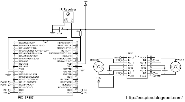
Remote controlled 2 DC motors using PIC16F887 and L293D circuit
As shown in the circuit diagram the IR receiver output is connected to RB0 pin which is external interrupt pin of the PIC16F887 microcontroller.
The L293D IC is used to drive both motors in the two directions, the speed of the two motors is controlled the two PWM signals which come from the microcontroller. PWM1 controls motor 1 speed and PWM2 controls motor 2 speed. Motor 1 direction is controlled with IN1 and IN2 pins of the L293D, these pins are connected to RD0 and RD1 of the PIC16F887. Motor 2 is controlled with pin IN3 and IN4 of the L293D, IN3 is connected to RD2 and IN4 is connected to RD3 of the microcontroller. When IN1 = IN2 = 0, motor 1 stops, when IN1 = 1 and IN2 = 0 motor 1 moves in the first direction, when IN1 = 0 and IN2 = 1 motor 1 moves in the second direction. The same thing for motor 2 with pins IN3 and IN4.
The 10K ohm resistor is used to minimize the IR receiver output noise.
In the circuit there are two voltage sources, one with 5V which supplies most of the circuit and the other one with 12V which supplies only the L293D IC. The 12V source depends on the motors nominal voltage.
In this project the PIC16F887 uses its internal oscillator and MCLR pin function is disabled.

Two DC motors control with NEC IR remote control CCS C code:
Project C code is as shown below. It has been tested with CCS PIC C compiler version 5.051.
PIC16F887 hardware external interrupt and Timer1 are used to decode the IR remote control. Timer1 is used to measure pulses and spaces widths and its interrupt (Timer1 interrupt) is used to reset the decoding process in case of very long pulse or space (time out). Timer1 is configured to increment every 1µs using the following command line:
setup_timer_1( T1_INTERNAL | T1_DIV_BY_2 );
But Timer1 module will not start until the microcontroller receives an interrupt on pin RB0 (interrupt edge from high to low).
The motor speed changes whenever the duty cycle of the PWM signal changes, and thus if the microcontroller receives speed up button code it will increment the duty cycle, then motor speed will be increased, and if the microcontroller receives speed down button code, the duty cycle will be decreased which causes the motor to decrease its speed.
At start up , both motors are stopped because all PORTD pins are zeroes with the command output_d(0); and when start/toggle direction button is pressed, the motor will start (if there is sufficient duty cycle otherwise the duty cycle have to be increased), and the same button pressed again the motor will change its direction of rotation.
The full C code is shown below.
// 2 Motors control with NEC IR remote control CCS C code
// Used MCU: PIC16F887
// Internal oscillator used @ 8MHz
// Used remote control: Car MP3 IR remote control
// PWM1 and PWM2 modules are used to control motor 1 and motor 2 speeds respectively
// http://ccspicc.blogspot.com/
// electronnote@gmail.com

#include <16F887.h>
#fuses NOMCLR NOBROWNOUT NOLVP INTRC_IO
#use delay(clock = 8MHz)

short nec_ok = 0, repeated = 0, m1_dir = 0, m2_dir = 0;
unsigned int8 nec_state = 0, i, duty1 = 0, duty2 = 0;
unsigned int32 nec_code;
#INT_EXT                                         // External interrupt
void ext_isr(void){
  unsigned int16 time;
  if(nec_state != 0){
    time = get_timer1();                         // Store Timer1 value
    set_timer1(0);                               // Reset Timer1
  }
  switch(nec_state){
    case 0 :                                     // Start receiving IR data (we're at the beginning of 9ms pulse)
      setup_timer_1( T1_INTERNAL | T1_DIV_BY_2 );   // Enable Timer1 module with internal clock source and prescaler = 2
      set_timer1(0);                             // Reset Timer1 value
      nec_state = 1;                             // Next state: end of 9ms pulse (start of 4.5ms space)
      i = 0;
      ext_int_edge( L_TO_H );                    // Toggle external interrupt edge
      break;
    case 1 :                                     // End of 9ms pulse
      if((time > 9500) || (time < 8500)){        // Invalid interval ==> stop decoding and reset
        nec_state = 0;                           // Reset decoding process
        setup_timer_1(T1_DISABLED);              // Stop Timer1 module
      }
      else
        nec_state = 2;                           // Next state: end of 4.5ms space (start of 562µs pulse)
      ext_int_edge( H_TO_L );                    // Toggle external interrupt edge
      break;
    case 2 :                                     // End of 4.5ms space
      if((time > 5000) || (time < 1500)){        // Invalid interval ==> stop decoding and reset
        nec_state = 0;                           // Reset decoding process
        setup_timer_1(T1_DISABLED);              // Stop Timer1 module
        break;
      }
      nec_state = 3;                             // Next state: end of 562µs pulse (start of 562µs or 1687µs space)
      if(time < 3000)                            // Check if previous code is repeated
        repeated = 1;
      ext_int_edge( L_TO_H );                    // Toggle external interrupt edge
      break;
    case 3 :                                     // End of 562µs pulse
      if((time > 700) || (time < 400)){          // Invalid interval ==> stop decoding and reset
        nec_state = 0;                           // Reset decoding process
        setup_timer_1(T1_DISABLED);              // Disable Timer1 module
      }
      else{
        // Check if the repeated code is for buttons 2, 3, 5 or 6
        if(repeated && (nec_code == 0x40BF807F || nec_code == 0x40BF40BF ||
                        nec_code == 0x40BFA05F || nec_code == 0x40BF609F)){
          repeated = 0;
          nec_ok = 1;                            // Decoding process is finished with success
          disable_interrupts(INT_EXT);           // Disable the external interrupt
          break;
        }
        nec_state = 4;                           // Next state: end of 562µs or 1687µs space
        ext_int_edge( H_TO_L );                  // Toggle external interrupt edge
        break;
      }
    case 4 :                                     // End of 562µs or 1687µs space
      if((time > 1800) || (time < 400)){         // Invalid interval ==> stop decoding and reset
        nec_state = 0;                           // Reset decoding process
        setup_timer_1(T1_DISABLED);              // Disable Timer1 module
        break;
      }
      if( time > 1000)                           // If space width > 1ms (short space)
        bit_set(nec_code, (31 - i));             // Write 1 to bit (31 - i)
      else                                       // If space width < 1ms (long space)
        bit_clear(nec_code, (31 - i));           // Write 0 to bit (31 - i)
      i++;
      if(i > 31){                                // If all bits are received
        nec_ok = 1;                              // Decoding process is finished with success
        disable_interrupts(INT_EXT);             // Disable the external interrupt
      }
      nec_state = 3;                             // Next state: end of 562µs pulse (start of 562µs or 1687µs space)
      ext_int_edge( L_TO_H );                    // Toggle external interrupt edge
  }
}
#INT_TIMER1                                      // Timer1 interrupt (used for time out)
void timer1_isr(void){
  nec_state = 0;                                 // Reset decoding process
  ext_int_edge( H_TO_L );                        // External interrupt edge from high to low
  setup_timer_1(T1_DISABLED);                    // Disable Timer1 module
  clear_interrupt(INT_TIMER1);                   // Clear Timer1 interrupt flag bit
}
void main(){
  setup_oscillator(OSC_8MHZ);                    // Set internal oscillator to 8MHz
  output_d(0);
  enable_interrupts(GLOBAL);                     // Enable global interrupts
  enable_interrupts(INT_EXT_H2L);                // Enable external interrupt
  clear_interrupt(INT_TIMER1);                   // Clear Timer1 interrupt flag bit
  enable_interrupts(INT_TIMER1);                 // Enable Timer1 interrupt
  setup_timer_2(T2_DIV_BY_16, 255, 1);           // Set PWM frequency to 488Hz
  setup_ccp1(CCP_PWM);                           // Configure CCP1 module as PWM
  setup_ccp2(CCP_PWM);                           // Configure CCP2 module as PWM
  set_pwm1_duty(0);                              // Set PWM1 duty sycle
  set_pwm2_duty(0);                              // Set PWM2 duty sycle
  while(TRUE){
    if(nec_ok){                                  // If the MCU receives a message from the remote control
      nec_ok = 0;                                // Reset decoding process
      nec_state = 0;
      setup_timer_1(T1_DISABLED);                // Disable Timer1 module
      // Motor 1
      if(nec_code == 0x40BF00FF && m1_dir){      // If button 1 is pressed (toggle rotation direction of motor 1)
        m1_dir = 0;
        nec_code = 0;
        output_high(PIN_D0);
        output_low(PIN_D1);
      }
      if(nec_code == 0x40BF00FF && !m1_dir){      // If button 1 is pressed (toggle rotation direction of motor 1)
        m1_dir = 1;
        output_low(PIN_D0);
        output_high(PIN_D1);
      }
      if(nec_code == 0x40BF40BF && duty1 < 255){ // If button 3 is pressed (increase motor 1 speed)
        duty1++;
        set_pwm1_duty(duty1);
      }
      if(nec_code == 0x40BF807F && duty1 > 0){   // If button 2 is pressed (decrease motor 1 speed)
        duty1--;
        set_pwm1_duty(duty1);
      }
      // Motor 2
      if(nec_code == 0x40BF20DF && m2_dir){      // If button 4 is pressed (toggle rotation direction of motor 2)
        m2_dir = 0;
        nec_code = 0;
        output_high(PIN_D2);
        output_low(PIN_D3);
      }
      if(nec_code == 0x40BF20DF && !m2_dir){     // If button 4 is pressed (toggle rotation direction of motor 2)
        m2_dir = 1;
        output_low(PIN_D2);
        output_high(PIN_D3);
      }
      if(nec_code == 0x40BF609F && duty2 < 255){ // If button 6 is pressed (increase motor é speed)
        duty2++;
        set_pwm2_duty(duty2);
      }
      if(nec_code == 0x40BFA05F && duty2 > 0){   // If button 5 is pressed (decrease motor 2 speed)
        duty2--;
        set_pwm2_duty(duty2);
      }
      enable_interrupts(INT_EXT_H2L);            // Enable external interrupt
    }
  }
}
The following video shows a hardware circuit of our project:


Interfacing DS3231 with PIC16F887 microcontroller


Hardware circuit for PIC16F887 and DS3231 RTC 
The datasheet of DS3231 RTC (real time clock) says that it is a low-cost, extremely accurate I2C real-time clock (RTC) with an integrated temperature compensated crystal oscillator (TCXO) and crystal. The DS3231 is much better than the DS1307 which means that it is a very good choice for persons who sell real time clock products.
The DS3231 RTC comes with an internal oscillator which means there is no need for a 32.768KHz crystal oscillator.
This topic shows the interfacing of the DS3231 RTC with PIC16F887 microcontroller with full adjustment of time and date parameters.
Like the DS1307, the DS3231 uses I2C protocol which uses two lines SCL and SDA. The PIC16F887 has a hardware I2C module where the SCL and SDA pins are mapped to RC3 and RC4 respectively.
Hardware Required:
  • PIC16F887 microcontroller
  • DS3231 (or DS3232) RTC -- Datasheet
  • 16x2 LCD screen
  • 2 x push button
  • 10K ohm variable resistor
  • 2 x 10K ohm resistors
  • 0.1µF capacitor (decoupling capacitor needed for the DS3231)
  • 3V coin cell battery
  • 5V voltage source
  • Protoboard
  • Jumper wires
Interfacing DS3231 with PIC16F887 microcontroller circuit:
Interfacing PIC16F887 with DS3231 RTC with set buttons circuit
As we can see in the circuit there is a 16x2 LCD to display time and date, this LCD is connected to PORTD. The SCL and SDA pins of the DS3231 are connected to SCL (RC3) and SDA (RC4) pins of the PIC16F887 microcontroller. Two pull-up resistors of 10K are needed for the SCL and SDA lines, if these two resistors are not connected to whole circuit will not work at all and the LCD may not display any thing.
The two buttons which are connected to pins RB0 and RB1, these buttons are used to set the time as well as the date as shown in the videos below.
The 3V cell battery is used as a backup to keep time and date running in case of main power failure. The circuit can work without this battery but its pin (#14) has to be grounded.
The internal oscillator of the PIC16F887 is used and MCLR pin function is disabled.

Interfacing DS3231 with PIC16F887 microcontroller CCS C code:
The C code below is for CCS PIC C compiler (tested with version 5.051).
Please read the DS3231 datasheet to understand the code.
In CCS C it is easy to initialize the I2C module of the PIC microcontroller using the following line:
#use I2C(master, I2C1, FAST = 100000)
Where:
master: set the microcontroller to the master mode
I2C1: use first I2C module (PIC16F887 has only one module)
FAST = 100000 : set the speed to100KHz
he DS3231 works with BCD format only and to convert the BCD to decimal and vise versa I used the following lines (example for minute variable):
minute = (minute >> 4) * 10 + (minute & 0x0F);                                  // Convert BCD to decimal
minute = ((minute / 10) << 4) + (minute % 10);                                  // Convert decimal to BCD
The full code is as the one below.
/* Real time clock using PIC16F887 & DS3231 (DS3232) CCS C code
   Read DS3231 RTC datasheet to understand the code!
   Internal oscillator used @ 8MHz
   http://ccspicc.blogspot.com/
   electronnote@gmail.com
*/

//LCD module connections
#define LCD_RS_PIN PIN_D0
#define LCD_RW_PIN PIN_D1
#define LCD_ENABLE_PIN PIN_D2
#define LCD_DATA4 PIN_D3
#define LCD_DATA5 PIN_D4
#define LCD_DATA6 PIN_D5
#define LCD_DATA7 PIN_D6
//End LCD module connections

#include <16F887.h>
#fuses NOMCLR NOBROWNOUT NOLVP INTRC_IO
#use delay(clock = 8MHz)
#include <lcd.c>
#use fast_io(B)
#use I2C(master, I2C1, FAST = 100000)

char time[] = "TIME:  :  :  ";
char calendar[] = "DATE:  /  /20  ";
unsigned int8  i, second, minute, hour, date, month, year;
void DS3231_display(){
  // Convert BCD to decimal
  second = (second >> 4) * 10 + (second & 0x0F);
  minute = (minute >> 4) * 10 + (minute & 0x0F);
  hour = (hour >> 4) * 10 + (hour & 0x0F);
  date = (date >> 4) * 10 + (date & 0x0F);
  month = (month >> 4) * 10 + (month & 0x0F);
  year = (year >> 4) * 10 + (year & 0x0F);
  // End conversion
  time[12]     = second % 10  + 48;
  time[11]     = second / 10  + 48;
  time[9]      = minute % 10  + 48;
  time[8]      = minute / 10  + 48;
  time[6]      = hour % 10  + 48;
  time[5]      = hour / 10  + 48;
  calendar[14] = year % 10 + 48;
  calendar[13] = year / 10  + 48;
  calendar[9]  = month % 10 + 48;
  calendar[8]  = month / 10 + 48;
  calendar[6]  = date % 10 + 48;
  calendar[5]  = date / 10 + 48;
  lcd_gotoxy(1, 1);                              // Go to column 1 row 1
  printf(lcd_putc, time);                        // Display time
  lcd_gotoxy(1, 2);                              // Go to column 1 row 2
  printf(lcd_putc, calendar);                    // Display calendar
}
void blink(){
  int8 j = 0;
  while(j < 10 && input(PIN_B0) && input(PIN_B1)){
    j++;
    delay_ms(25);
  }
}
unsigned int8 edit(parameter, xx, yy){
  while(!input(PIN_B0));                         // Wait until button RB0 is released
  while(TRUE){
    while(!input(PIN_B1)){                       // If button RB1 is pressed
      parameter++;
      if(i == 0 && parameter > 23)               // If hours > 23 ==> hours = 0
        parameter = 0;
      if(i == 1 && parameter > 59)               // If minutes > 59 ==> minutes = 0
        parameter = 0;
      if(i == 2 && parameter > 31)               // If date > 31 ==> date = 1
        parameter = 1;
      if(i == 3 && parameter > 12)               // If month > 12 ==> month = 1
        parameter = 1;
      if(i == 4 && parameter > 99)               // If year > 99 ==> year = 0
        parameter = 0;
      lcd_gotoxy(xx, yy);
      printf(lcd_putc,"%02u", parameter);        // Display parameter
      delay_ms(200);                             // Wait 200ms
    }
    lcd_gotoxy(xx, yy);
    lcd_putc("  ");
    blink();
    lcd_gotoxy(xx, yy);                          // Display two spaces
    printf(lcd_putc,"%02u", parameter);          // Display parameter
    blink();
    if(!input(PIN_B0)){                          // If button RB0 is pressed
      i++;                                       // Increament 'i' for the next parameter
      return parameter;                          // Return parameter value and exit
    }
  }
}
void main(){
  setup_oscillator(OSC_8MHZ);                    // Set internal oscillator to 8MHz
  port_b_pullups(3);                             // Enable internal pull-ups for RB0 & RB1
  lcd_init();                                    // Initialize LCD module
  lcd_putc('\f');                                // LCD clear
  while(TRUE){
    if(!input(PIN_B0)){                          // If RB0 button is pressed
      i = 0;
      hour = edit(hour, 6, 1);
      minute = edit(minute, 9, 1);
      date = edit(date, 6, 2);
      month = edit(month, 9, 2);
      year = edit(year, 14, 2);
      // Convert decimal to BCD
      minute = ((minute / 10) << 4) + (minute % 10);
      hour = ((hour / 10) << 4) + (hour % 10);
      date = ((date / 10) << 4) + (date % 10);
      month = ((month / 10) << 4) + (month % 10);
      year = ((year / 10) << 4) + (year % 10);
      // End conversion
      // Write data to DS3231 RTC
      i2c_start();                               // Start I2C protocol
      i2c_write(0xD0);                           // DS3231 address
      i2c_write(0);
      i2c_write(0);                              // Reset sesonds and start oscillator
      i2c_write(minute);                         // Write minute value to DS3231
      i2c_write(hour);                           // Write hour value to DS3231
      i2c_write(1);                              // Write day value (not used)
      i2c_write(date);                           // Write date value to DS3231
      i2c_write(month);                          // Write month value to DS3231
      i2c_write(year);                           // Write year value to DS3231
      delay_ms(200);                             // Wait 200ms
    }
    i2c_start();                                  // Start I2C protocol
    i2c_write(0xD0);                              // DS3231 address
    i2c_write(0);                                 // Send register address
    i2c_start();                                  // Restart I2C
    i2c_write(0xD1);                              // Initialize data read
    second = i2c_read(1);                         // Read seconds from register 0
    minute = i2c_read(1);                         // Read minuts from register 1
    hour   = i2c_read(1);                         // Read hour from register 2
    i2c_read(1);                                  // Read day from register 3 (not used)
    date   = i2c_read(1);                         // Read date from register 4
    month  = i2c_read(1);                         // Read month from register 5
    year   = i2c_read(0);                         // Read year from register 6
    i2c_stop();                                   // Stop I2C protocol
    DS3231_display();                             // Diaplay time & calendar
    delay_ms(50);
  }
}
The following video shows the interfacing of PIC16F887 with the DS3231 in real hardware circuit:


And the following video shows Proteus simulation:


PIC16F887 and DS3231 RTC Proteus simulation file download:
Download

Sunday, July 16, 2017

Two motors control using PIC16F887 and L293D


The L293D quadruple half-H drivers chip allows us to drive 2 motors in both directions, and with the two PWM modules on the PIC16F887 microcontroller we can easily control the rotation speed of the two motors. (PWM: Pulse Width Modulation).
This small example shows how to implement a control circuit which controls speed and direction of rotation using PIC16F887 microcontroller and L293D IC.
The microcontroller PIC16F887 has one ECCP (Enhanced Capture/Compare/PWM) module and one CCP module. The two modules can be configured as PWM modules to generate two independent PWM signals (always with the same frequency). The speed of each motor can be controlled with the variation of the duty cycle of the PWM signal. The output pins of PWM1 and PWM2 are RC2 and RC1 respectively.
Required Components:
  • PIC16F887 microcontroller
  • 2 x DC motor (I used motors of 12V)
  • L293D motor driver
  • 2 x 10K ohm potentiometer
  • 5V Power source
  • 12V Power source (In case of 12V DC motors)
  • Breadboard
  • Jumper wires
Two motors control using PIC16F887 and L293D circuit:
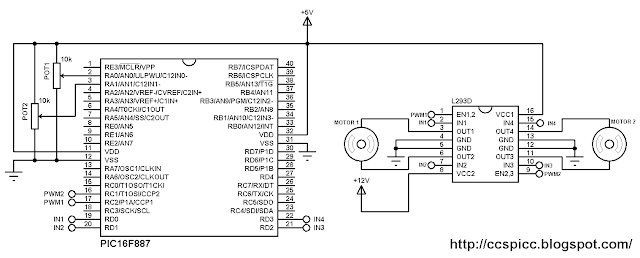
Example circuit diagram is shown below.
Two DC motors control using PIC16F887 and L293D circuit diagram
In the circuit there are two potentiometers POT1 and POT2 which are used to control the speed as well as the direction of rotation of motor 1 and motor 2 respectively. POT1 is connected to analog channel 0 (AN0) and POT2 is connected to analog channel 1 (AN1).
PWM1 pin (RC2) is connected to EN1,2 pin (#1) and PWM2 pin (RC1) is connected to EN2,3 pin (#9) of the L293D. The other L293D pins which are IN1, IN2, IN3 and IN4 are connected to RD0, RD1, RD2 and RD3 respectively.
Motor 1 rotation speed is controlled by PWM1 and its direction of rotation is controlled by pins IN1 and IN2. If IN1 and IN2 are zeroes the motor stops, if IN1 = 1 and IN2 = 0 the motor rotates in the one direction, if IN1 = 0 and IN2 = 1 the motor rotates in the other direction.
The same thing for motor 2 with pins PWM2, IN3 and IN4.
In the circuit there are two power supply sources, 5V and 12V. The 5V supplies most of the circuit including the microcontroller whereas the 12V supplies one pin of the L293D (VCC2). The 12V power supply source depends on the motor nominal voltage, for example if the motor voltage is 5V, VCC2 pin should be connected to +5V source.
In this example PIC16F887 uses its internal oscillator and MCLR pin function is disabled.
Two motors control using PIC16F887 and L293D CCS C code:
In this example we've two potentiometers POT1 and POT2 connected to AN0 and AN1. Each potentiometer controls speed and rotation direction of one motor. In the code there are three intervals after reading and saving the analog value. The first interval is [ 0, 500 [ which controls the motor speed in the first direction where the maximum speed is when the analog value = 0. The second interval is [ 500, 523 ], here the motor stops. The last interval is ] 523, 1023] where the motor speed is controlled in the other direction and the maximum speed when the analog value = 1023. 10-Bit ADC resolution is used.
Timer2 module is configured to generate PWM signals of 1KHz whith a resolution of 8.96 bits :
setup_timer_2(T2_DIV_BY_16, 124, 1);
Where: T2_DIV_BY_16 is Timer2 prescaler
              124 is Timer2 preload value
              1 is Timer2 postoscaler (not used in calculations)
The PWM frequency can be calculated using the following equation:
PWM Period = [(PR2) + 1] * 4 * TOSC * (TMR2 Prescale Value)
Where the PWM frequency = 1/ PWM period
PR2: Timer2 preload value
TOSC = 1/MCU frequency (in this example MCU frequency = 8MHz)
The resolution of the PWM signal can be calculated using the following equation:
               log[4(PR2 + 1)]
Resolution = ---------------------   bits
                  log(2)
// Control of 2 motors using PIC16F887 microcontroller CCS C code
// Internal oscillator used @ 8MHz
// http://ccspicc.blogspot.com/
// electronnote@gmail.com

#include <16F887.h>
#device ADC = 10
#fuses NOMCLR, NOBROWNOUT, NOLVP, INTRC_IO
#use delay(clock = 8MHz)

signed int16 i, j;
void main(){
  setup_oscillator(OSC_8MHZ);                    // Set internal oscillator to 8MHz
  setup_adc(ADC_CLOCK_INTERNAL);                 // ADC module uses its internal oscillator
  setup_adc_ports(sAN0 | sAN1);                  // Configure AN0 & AN1 as analog input pins
  setup_timer_2(T2_DIV_BY_16, 124, 1);           // Set PWM frequency to 1KHz with a resolution of 8.96-bit
  setup_ccp1(CCP_PWM);                           // Configure CCP1 module as PWM
  setup_ccp2(CCP_PWM);                           // Configure CCP2 module as PWM
  set_pwm1_duty(0);                              // Set PWM1 duty cycle
  set_pwm2_duty(0);                              // Set PWM2 duty cycle
  while(TRUE){
    set_adc_channel(0);                          // Select channel AN0
    delay_ms(100);
    i = read_adc();                              // Read analog value from channel '0' and store it in 'i'
    set_pwm1_duty(abs(i - 511));                 // Set PWM1 duty cycle (abs => absolute value
    set_adc_channel(1);                          // Select channel AN1
    delay_ms(100);
    j = read_adc();                              // Read analog value from channel '1' and store it in 'j'
    set_pwm2_duty(abs(j - 511));                 // Set PWM2 duty cycle (abs => absolute value
    if(i > 523){
      output_high(PIN_D0);
      output_low(PIN_D1);
    }
    else{
      if(i < 500){
        output_low(PIN_D0);
        output_high(PIN_D1);
      }
      else{
        output_low(PIN_D0);
        output_low(PIN_D1);
      }
    }
    if(j > 523){
      output_high(PIN_D2);
      output_low(PIN_D3);
    }
    else{ 
      if(j < 500){
        output_low(PIN_D2);
        output_high(PIN_D3);
      }
      else{
        output_low(PIN_D2);
        output_low(PIN_D3);
      }
    }
  }
}
Video: