The RTOS (Real Time operating System) allows more than one task to run simultaneously (in parallel), for example reading from an analog channel, blinking an LED, setting the duty cycle of a PWM signal.....
This small article shows an RTOS example using PIC16F887 microcontroller and CCS PIC C compiler.
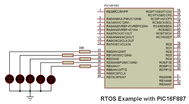
In this example we've 5 LEDs connected to the PIC16F887 microcontroller as shown in the circuit below. It is designed that the 5 LEDs are blinking but each one has its blinking frequency.
In this example the PIC16F887 MCU uses its internal oscillator which is configured in the software @ 4MHz and MCLR pin function is disabled.
RTOS Example with PIC16F887 microcontroller CCS C code:
As mentioned above our RTOS has 5 LEDs with different frequencies (periods = 1/frequency).
The first LED which is connected to RB0 pin has the following task with a period of 500ms (250ms x 2):
#task(rate = 250ms, max = 50ms)
void led1(){
output_toggle(PIN_B0);
}
The same thing for the other LEDs.
In CCS C compiler the RTOS is configured using the following line:
#use rtos(timer = 0, minor_cycle = 50ms)
Here Timer0 is selected for the RTOS but other timers (Timer1 or Timer2) can also be used.
The complete C code is the one below.
// RTOS example for PIC16F887 with CCS PIC C compiler
// PIC16F887 internal oscillator used @ 4MHz
// Timer0 is used for the RTOS
// http://ccspicc.blogspot.com/
// electronnote@gmail.com

#include <16F887.h>
#fuses NOMCLR, NOBROWNOUT, NOLVP, INTRC_IO
#use delay(clock = 4MHz)
#use fast_io(B)
#use rtos(timer = 0, minor_cycle = 50ms)

#task(rate = 250ms, max = 50ms)                  // 1st RTOS task (executed every 250ms)
void led1(){
  output_toggle(PIN_B0);
}
#task(rate = 500ms, max = 50ms)                  // 2nd RTOS task (executed every 500ms)
void led2(){
  output_toggle(PIN_B1);
}
#task(rate = 750ms, max = 50ms)                  // 3rd RTOS task (executed every 750ms)
void led3(){
  output_toggle(PIN_B2);
}
#task(rate = 1000ms, max = 50ms)                 // 4th RTOS task (executed every 1000ms)
void led4(){
  output_toggle(PIN_B3);
}
#task(rate = 1250ms, max = 50ms)                 // 5th RTOS task (executed every 1250ms)
void led5(){
  output_toggle(PIN_B4);
}
void main(){
  setup_oscillator(OSC_4MHZ);                    // Set the internal oscillator to 8MHz
  output_b(0);                                   // All PORTB register pins are zeros
  set_tris_b(0);                                 // Configure PORTB pins as outputs
  rtos_run();                                    // Start all the RTOS tasks
}
The following video shows Proteus simulation of the RTOS example:
Proteus simulation file can be downloaded from the following link:
Download

